Audio Power Amplifier with TDA2050
- Hristo
- xristost@yahoo.com
- 59.774 Views
- moderate
- Tested
This project is an audio amplifier based on TDA2050 and LM1875.
Description
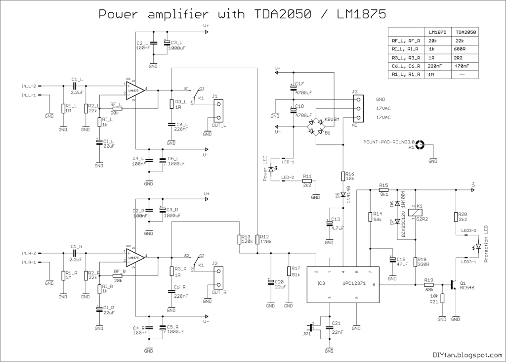
This is not an ordinary project, but an attempt to make a PCB that is suitable for TDA2050 andLM1875 and has all the necessary circuitry on board – power supply, speaker protection, delayed turn-on and fast turn-off. This is achieved using the convenient uPC1237 IC.
TDA2050 and LM1875 are pin to pin compatible, the differences in their schematics are the values of a couple resistors and one capacitor. All this allows to make an universal circuit board, suitable for any of these two ICs.
It is 2x30W, but it depend of the power supply voltage and the impedance of the speakers connected to the output.
Schematic
Parts List
B1 KBU8M FBU4
C1 100nF C050-024X044
C2 100nF C050-024X044
C3 1000uF E5-10,5
C4 1000uF E5-10,5
C6 2.2uF C050-075X075
C7 220nF C050-030X075
C8 22uF E3,5-8
C9 100nF C050-024X044
C10 100nF C050-024X044
C11 1000uF E5-10,5
C12 1000uF E5-10,5
C13 4.7uF E2,5-6
C14 2.2uF C050-075X075
C15 220nF C050-030X075
C16 22uF E3,5-8
C17 4700uF E7,5-18
C18 4700uF E7,5-18
C19 47uF E2,5-7
C20 22uF E3,5-8
C21 22nF C050-025X075
D5 1N4148 DO35-7
D6 1N4004 DO41-10
D7 BZX85C12V DO41Z10
H1 MOUNT-PAD-ROUND3.0 3,0-PAD
IC1 LM1875 T05D
IC2 LM1875 T05D
IC3 UPC1237 SOP8
IN 6410-02
IN1 6410-02
J1 OUT1 AC2
J2 OUT2 AC2
J3 AC AC3
JP1 JP1
K1 G2R2 G2R2
LED 6410-02
LED2 LED5MM
LED3 6410-02
R1 1k 0207/2V
R2 20k 0207/12
R3 22k 0207/7
R4 1M 0207/7
R5 1R 0414V
R6 1k 0207/2V
R7 20k 0207/12
R8 22k 0207/7
R9 1M 0207/7
R10 1R 0414V
R11 2k2 0207/7
R12 120k 0207/7
R13 120k 0207/10
R14 56k 0207/7
R15 9k1 0207/7
R16 10k 0207/7
R17 92k 0207/10
R18 330R 0207/10
R19 68k 0207/7
R20 3k9 0207/10
R21 10k 0207/7
T2 MPSA42 TO92-EBC
Photos


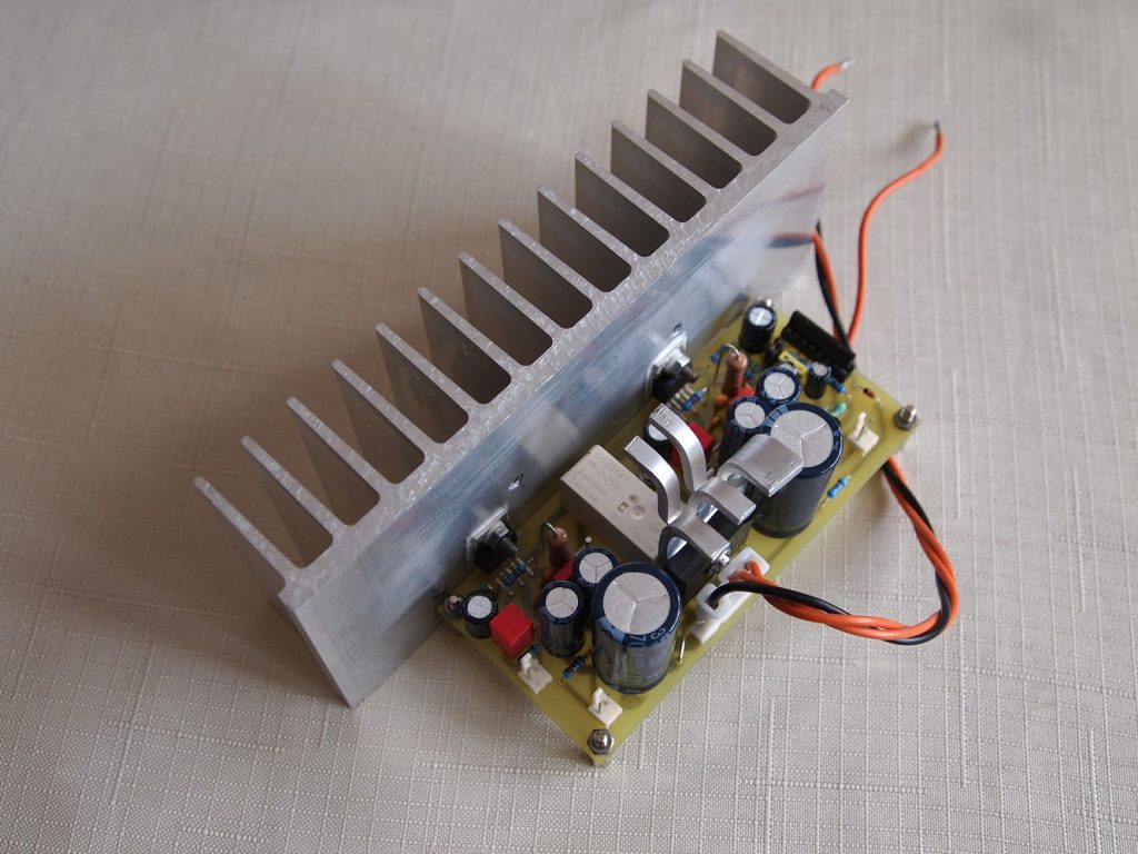
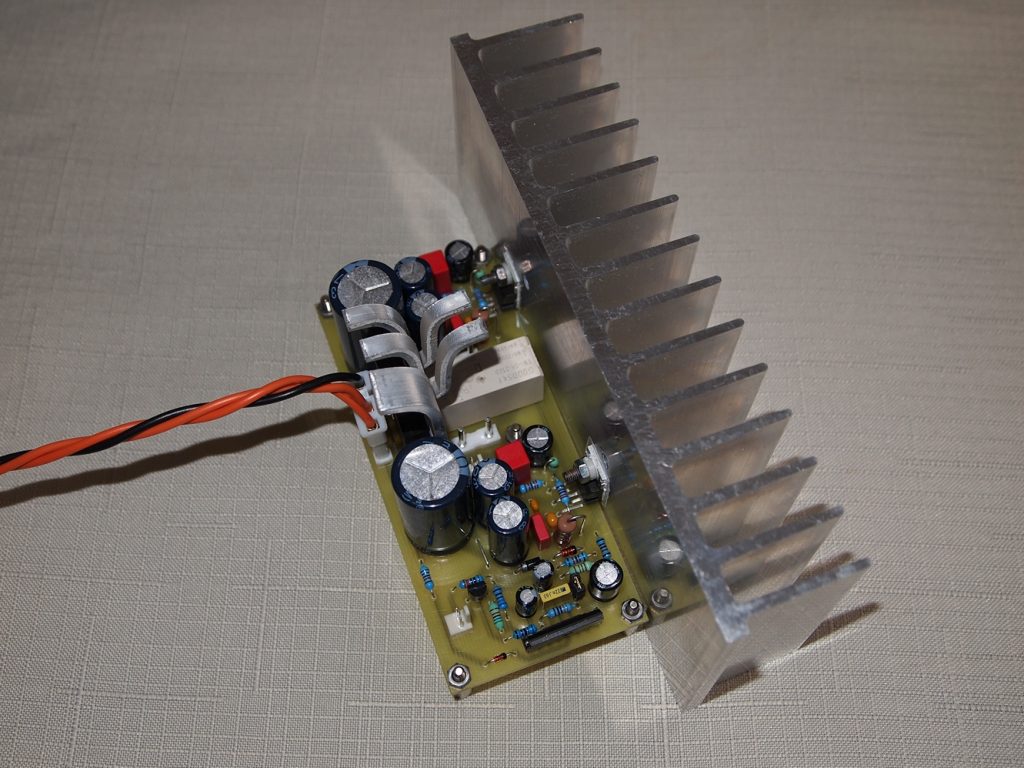
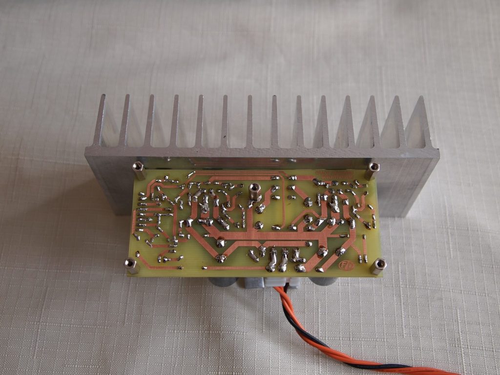
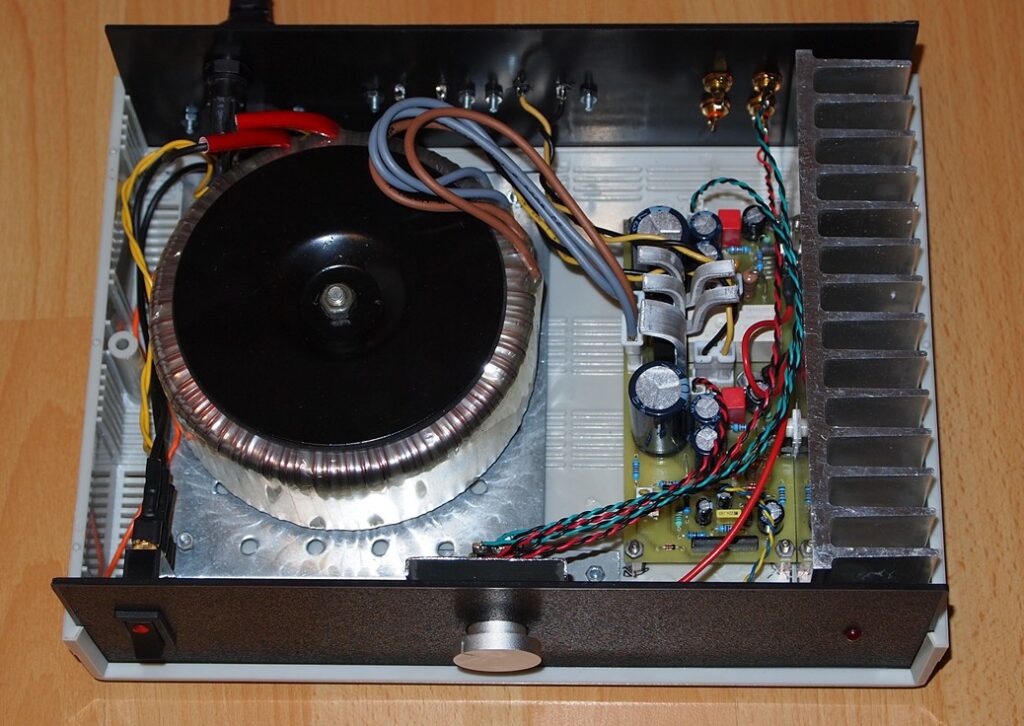
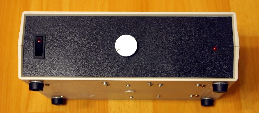
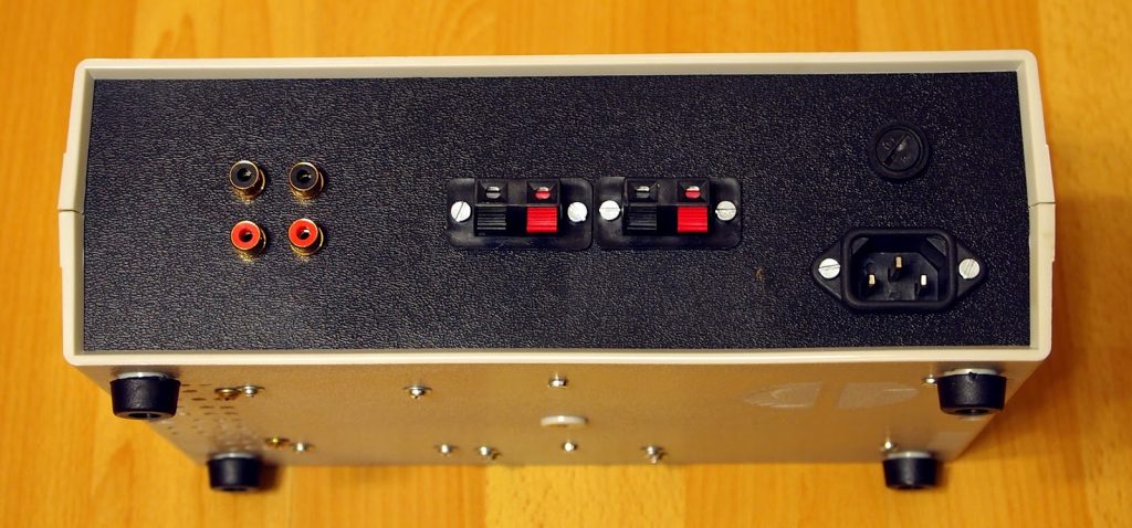
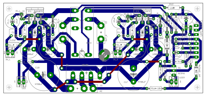
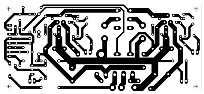
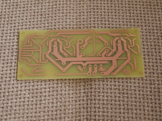



The TDA2050 is not available at both of the largest electronics parts distributors in North America. Is it obsolete?
Its available in India (even TDA2030 for 0.25$), but can’t say same whether they are fake or not. I’m currently using TDA2030. If you need any help email me – availlyrics at the rate rediffmail dot com
Bridge transformator less??
Bridge rectifier B1 is rated at 8A and we recommend using same rating for this project.
How much supply voltage can be given to a cheap tda2050 or tda2030A ?
TDA2050 can accept a maximum absolute supply voltage o +/-25V and TDA2030A +/-22V
schematic versus pictures showned results was 2 blown capacitors, Q1 also not resulting good sounds due to upside down, IC 3 is just a bypass line for speakers, wasting time, but thats ok, atleast i’d tried, next time put the exact voltage recommended on each capacitors, long live and stay safe, thank you
Sir Chris, please guide what values of capacitors you used, am trying to build this project too. your guide will be appreciated