audioguru
-
Posts
12,026 -
Joined
-
Last visited
-
Days Won
13
3 Followers
.thumb.jpg.4fdfd13c917ffeba685081d4182a6e18.jpg)


audioguru's Achievements
")
Newbie (1/14)
39
Reputation
-
 EJE reacted to a post in a topic:
0-30 Vdc Stabilized Power Supply
EJE reacted to a post in a topic:
0-30 Vdc Stabilized Power Supply
-
 spur reacted to a post in a topic:
0-30V Stabilized Power Supply
spur reacted to a post in a topic:
0-30V Stabilized Power Supply
-
spur reacted to a post in a topic:
0-30V Stabilized Power Supply
-
 Ishwor reacted to a post in a topic:
0-30 Vdc Stabilized Power Supply
Ishwor reacted to a post in a topic:
0-30 Vdc Stabilized Power Supply
-
Stereo is recorded on 2 channels and surround sound uses 4 or 5 channels. There are some Oriental ICs that produce fake surround sound when the input is ordinary stereo. Some people think it sounds real.
-
frisil reacted to a post in a topic:
0-30V 0-3A Latest Data
-

power supply 0-30 volt stailized power supply
audioguru replied to shaknitboss's topic in Electronic Projects Design/Ideas
Many power supplies use a fan blowing past the heatsink so that the heatsink can be smaller. -
Whizard reacted to a post in a topic:
0-30 volt stailized power supply
-
power supply 0-30 volt stailized power supply
audioguru replied to shaknitboss's topic in Electronic Projects Design/Ideas
Your 0.33 ohm resistor R7 with 2A in it has a voltage across it of 0.33 x 2= 0.66V. The current-setting circuit in the 30V/3A power supply has 0.47 ohms x 3A= 1.41V across it. Your current-setting circuit needs to be calculated to show 2A when its pot is set near maximum. Only one R7 is used (not two in parallel). -
power supply 0-30 volt stailized power supply
audioguru replied to shaknitboss's topic in Electronic Projects Design/Ideas
R7 has nothing to do with the output transistors. Instead R7 senses the amount of output current and sends its sensing voltage to the current adjustment opamp. Each of your output transistors need a series 0.33 ohm emitter resistor so that the two transistors are better matched to share the heating. -
power supply 0-30 volt stailized power supply
audioguru replied to shaknitboss's topic in Electronic Projects Design/Ideas
The parallel transistors in the circuit you posted do not have series emitter resistors so the ones with high gain take a high current and the ones with a low gain take a low current. Emitter resistors help to match the transistors. This is how the output transistors are connected in parallel: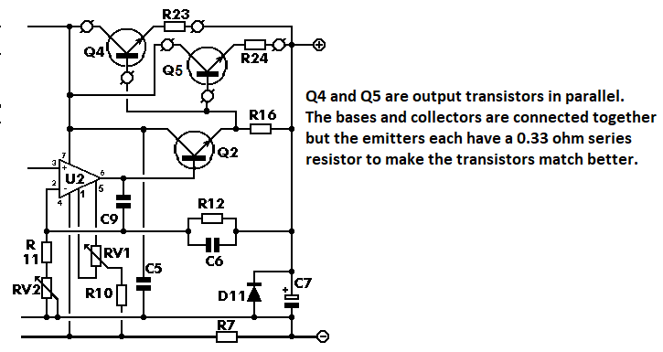
-
The datasheet of the ULN2003 shows that the saturation voltage loss is 1.4V. Then if the battery is 3.7v the motor gets only 2.3v but if the battery is 7.4V then the motor gets 6V. You did not say how much voltage and current the motor needs. You did not say what is the stalled current of the motor. Stalled is when something stops the motor from turning, which happens the moment it is powered. If the stalled current is higher than 1A (two ULN2003 outputs in parallel) then the ULN2003 will burn out.
-
power supply 0-30 volt stailized power supply
audioguru replied to shaknitboss's topic in Electronic Projects Design/Ideas
The very old circuit you posted works poorly. TR3 is its output transistor and it gets too hot. Add a second 2N3055 transistor parallel with TR3 to share the heat and add a 0.33 ohms/2W resistor in series with each emitter to the output. The transistors collectors can be connected directly together by the heatsink if the heatsink is insulated from any other part of the circuit. If you want a 0V to -30V, 2mA to 3A power supply then make a second one of this project and use its +30V output as 0V and use its 0V output as 0V to -30V. A center-tapped transformer will produce an AC output, not DC and not variable. -
power supply 0-30 volt stailized power supply
audioguru replied to shaknitboss's topic in Electronic Projects Design/Ideas
Sorry, I was wrong, you are correct. The peak of 24V RMS is 33.9V not 40V. The peak of the 28V RMS transformer I recommended is 40V. Then the full load drops the rectified voltage to 38VDC with ripple and the losses in the circuit have enough extra voltage for the output to be well-regulated 30VDC at 3A. -
power supply 0-30 volt stailized power supply
audioguru replied to shaknitboss's topic in Electronic Projects Design/Ideas
If the transformer is rated at 24VAC/2A then it provides a maximum power of 24V x 2A= 48VA. But if the output is 30V at 2.0A then the load uses 30V x 2A= 60VA plus heating power. The peak of 24VAC is 40V which feeds the bridge rectifier which charges the main filter capacitor to the peak voltage minus the rectifier forward voltage. So then the transformer must produce 40V at 2.0A= 80VA which is much more than the overloaded 48VA. 80VA/24V= 3.33A, not 2A. For a regulated output of 30.0VDC at 3A then I recommended using a transformer rated at 28VAC/4.3A. For an output current of 3A then you must look at how much heat is produced by the single output transistor which is why I recommended using two output transistors to share the heat. Edited with strike-throughs. -
Use a separate +5V supply to power the voltage meter and current meter. Connect the grounds of both meters to the (-) output of the power supply being measured. The current meter can measure the negative voltage across the 0.47 ohms R7 of the power supply being measured, then the current meter does not produce an additional voltage drop that ruins the good voltage regulation. R7 produces a voltage of 1.41V for 3A or 0.47V for 1A. You will need to make a voltage divider to reduce the 0.47V to 0.1V for the input of the current meter. Disconnect the (-) segment of the current meter display.
-
Need help with using a transistor or triac as a switch
audioguru replied to MAJ's topic in Projects Q/A
Your simulation is cheating because it uses a very high base voltage that has almost unlimited current and no voltage drop. -
Need help with using a transistor or triac as a switch
audioguru replied to MAJ's topic in Projects Q/A
Same question again but on this forum. Here you forgot to say which relay you will use so we do not know its coil current then we cannot calculate how much input current a transistor needs. You also did not say how much current the 1.2V timer can produce which might not be enough current to drive the transistor. 1.2V is probably too low to activate a photo-triac. -
The 24VAC transformer probably produces 25VAC with a light load on the project. Then its rectified and filtered output is +34V and -5.6V which power the opamps. At times the voltages are higher. Your transformer will be overloaded if its power rating is 105VA or less (24V at 4.4A).. The old TL081 opamps have an absolute maximum allowed supply of a total of only 36V so they will not last long. Replace the opamps with TLE2141 opamps that have a maximum allowed supply of 44V. Many of the resistors and the driver transistor in the original project are overloaded. Upgrade them. The main filter capacitor C1 value is much too low, upgrade it.
-
Need Heaphone/Mic Amp Circuitry
audioguru replied to jknightandkarr's topic in Electronic Projects Design/Ideas
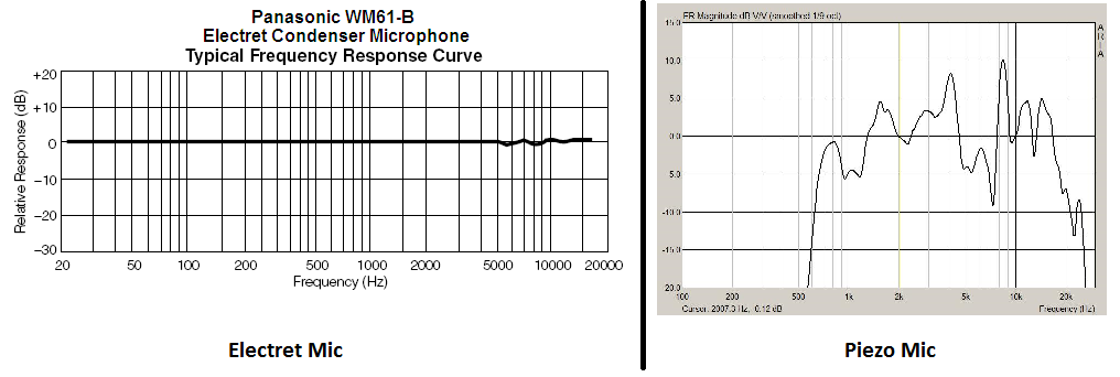
Software will not test the frequency response of a mic. You need calibrated sounds at different frequencies to do it. the manufacturer should have shown a frequency response graph like these ones: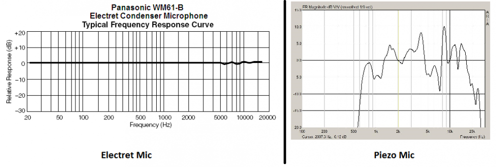
-
Need Heaphone/Mic Amp Circuitry
audioguru replied to jknightandkarr's topic in Electronic Projects Design/Ideas
A frequency response spec must include how much the levels deviate. Plus and minus 30dB is horrible but 2dB is pretty good. If they do not spec the plus and minus dBs then assume it is horrible. If you have background noise then you can turn down the volume. Using filters to cut frequencies you cannot hear will not reduce background noise. Instead you can cut all high audio frequencies to reduce hiss which will make words unintelligible and cut low audio frequencies so that guys voices sound like chipmunks. Audio opamps have low noise, "general purpose" opamps produce lots of noise. Your choice.