audioguru
-
Posts
12,026 -
Joined
-
Last visited
-
Days Won
13
Content Type
Profiles
Forums
Events
Everything posted by audioguru
-

Help interpreting Circuit schema please...
audioguru replied to giph's topic in Electronic Projects Design/Ideas
Yes, the pots short circuit the input signals when turned down because they are shown wired backwards, instead of wired like volume controls. -
Sorry, I do not have time to modify this power supply for you.
-
Sine you need a maximum output of only 15V and since most ordinary opamps have a maximum supply voltage of 36V then use an 18V transformer and the -5.6V negative supply as in the original project. The BD139 driver transistor and two 2N3055 output transistors in the latest version of this project should be used and the value of the resistor in series with the voltage calibration trimmer must be increased to set the maximum output to +15V.
-
I think this old circuit should be kissed goodbye and be buried.
-
I cannot see which connects to what. Can you provide a schematic?
-
The original circuit should work fine up to 15V at 1A if you replace the old opamps with the newer higher voltage ones. You probably should recalculate the resistors that set the maximum voltage and current outputs. If the Chinese kit uses the transistor that shorts the opamp output when the power is turned off then the resistors that feed the transistor need to be recalculated for the reduced voltage. I have used perforated stripboard for many projects including very complicated ones. The copper strips are cut to length with a drill-bit and become almost half the wiring of a pcb. The parts and a few short jumper wires become the remainder of the wiring. Only one wire is in each hole so changing a part is easy like on a pcb.
-
There are a few completely different types of phones and you do not say which one. Landline phone, wireless phone and cell phone. Take one apart and look inside then count the components. Why???
-
If the battery is good then it should power the circuit for a few hours when it is fully charged.
-
When the negative supply collapses to 0V when the positive supply is still 37.8V then the current in both resistors in series is 37.8V/(12k + 160 ohms)= 3.1mA. If the base is +0.65V then the current in the 160 ohms needs to be 0.65V/160 ohms= 4.1mA so the 160 ohms resistor value and the negative supply voltage are too low. I removed Q1 and somebody else later added it back in wrongly.
-
The battery is powering the opamp and LED when the solar panel is dark. You did not say a part number for the opamp, Mosfet or driver so we do not know if they will work from only 3.2V to 4.2V. The 3W LED might use a current of 3W/4.2V= 0.7A and maybe your opamp is actually an audio power amp that has a high current. Then the battery is drained in a few hours. You learn by reading the datasheets and selecting parts that work together, not by having errors and more errors.
-
The OPA541 shows in its datasheet that if its positive supply is your 48VAC rectified to make +66VDC, its required negative supply is -6V and its output is 0V (shorted or set to a low voltage) then the output transistor in it has a voltage of 66V across it and figure 11 shows a max allowed output current of only 0.35A if it has a huge heatsink. If it has a positive supply of +36V and a negative supply of -6V and its output voltage is set low then its maximum allowed output current is 2.5A if it has a huge heatsink. If it has the +36V, -6V supply and its output is set to +26V then its max allowed output current will be 7.5A if it has a huge heatsink.
-
Did you know that Chinese companies (ebay, Aliexpress, Banggood, Amazon and others) have copied the original defective Greek kit and used the wrong opamps and resistors that burn up? Their kits of the original project are very cheap. They use some Oriental transistors instead of the original ones.
-
The original project used a 24VAC transformer and TL081 opamps that have a maximum allowed supply of 36V. Since the project was not able to produce 30VDC at 3A because the supply voltage was too low, I changed the transformer to 28VAC and changed the opamps to TLE2141 that have a maximum allowed supply of 44VDC. Please post a video of your TLE2141 opamps blowing up if you power them from the 66VDC produced from rectifying the 48VAC from your wrong transformer. Or just parallel the two 24VAC secondaries which produces a rectified 32VDC so that the maximum regulated output from the project will be about 25VDC at 3A. The TLE2141 U2 gets warm, not hot because its output current is fairly low since it drives the driver transistor Q2 that drives the output transistors to 3A.
-
One 2N3055 transistor overheats in the original circuit that used a 24VAC transformer and produces 25VDC at 3A. Therefore I used higher voltage opamps, a 28V 4.2A transformer, a more modern driver transistor Q2 that can be cooled well and two 2N3055 transistors to share the heat on a very large heatsink. Some people added a fan and a smaller heatsink instead of a huge heatsink. If you connect the two 24V windings of your transformer in series and use the centertap as 0V then its output voltage will be 24VAC x 1.414= 34V minus the 1V for the two rectifiers then the supply voltage will be too low because the circuit needs a 28VAC transformer. Your transformer voltage is too high so it cannot be used for this project. Or you could parallel the two 24VAC windings or with the centertap as above then the maximum regulated output voltage will be 25VDC at 3A.
-
Sorry, I did not see the 48VAC total voltage. The maximum allowed current from the 48V transformer is only 3.33A but for an output from the project of 3A DC, the transformer must produce 3 x 1.414= 4.2A, because the rectified 48V produces 66VDC at 3A which is 198VA. But the transformer is rated at only 48V x 3.33= 160VA. Since the voltage is almost double what is needed then the heating of the parts is about 3.5 times more than with a suitable 28V or 30V transformer.
-
The 24VAC transformer has an output voltage too low for this power supply to produce 30VDC at 3A. The regulation will fail and there will be lots of ripple in the output at and above about 25V at 3A. I recommended a 28VAC or 30VAC transformer and higher voltage opamps years ago. For an output up to 5A then the transformer max output current should be 7A or more, the main filter capacitor C1 value should be about 17000uF or more, there should be 3 output transistors each with its own emitter resistor, a larger heatsink for the output transistors and change the value of R7 from 0.47 ohms to 0.27 ohms. I finished making improvements on this project in July, 2014 but others have made more changes.
-
The TIP31 is 83 times slower than the BD139 that I recommend that has almost the same speed as the original 2N2219 that got too hot as Q2. Then the TIP31 will probably cause oscillation.
-
Opamp U2 has a DC voltage gain of typically 200 thousand and its negative feedback connects directly to the output with R12. The negative feedback sets the actual gain at 2.68 times so if the output tries to decrease 1V then the actual output decrease will be only 13.4 micro volts which is almost nothing. Maybe your wiring (solderless breadboard?) has a voltage drop that the opamp is correcting. Transistor Q1 is simply an on-off switch that should be off when the power supply is powered and working. The TIP31 is larger than it needs to be but should work fine. your changed values of R15 and R4 are fine.
-
Lots of people made pcb designs for this modified circuit. I did not use one and I did not look at them. Sorry, I also did not look at yours.
-
How to make Audio power Amplifier Circuit
audioguru replied to Aman bharti's topic in Electronic Projects Design/Ideas
The output of the voltage regulator and positive supply for the LM386 and Arduino all need a capacitor to ground to prevent oscillations. -
How to make Audio power Amplifier Circuit
audioguru replied to Aman bharti's topic in Electronic Projects Design/Ideas
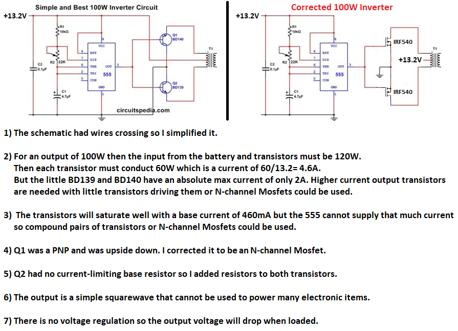
You talk about adding a resistor to make the transistor amplify but it reduces the signal and you do not say the value of the resistor. Of course it will not amplify if the resistor value is calculated wrong. What value did you use for the added collector resistor? The inverter was completely wrong but my corrections with the Mosfets is also completely wrong because both conduct at the same time. The original circuit will produce a low output power with the PNP shown as an emitter-follower without the NPN transistor working. Most simple inverters use a CD4047 IC instead of a 555 IC. The CD4047 has two outputs that have opposite polarities to drive the same kind of transistor on each output. The transistors are used as switches instead of as emitter-followers. An inverter uses a voltage sensor and negative feedback for voltage regulation. Didn't you look at the datasheet of the LM386 that says its minimum allowed supply is 4V to 5V, not 3V? Maybe you are lucky to find one that works at 3V but its output power will be extremely low. Here is a simple inverter with a CD4047 oscillator and Mosfets: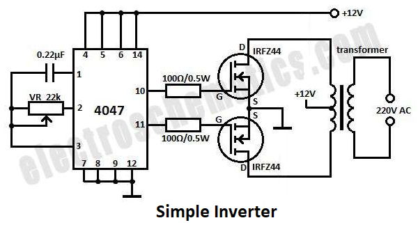
-
How to make Audio power Amplifier Circuit
audioguru replied to Aman bharti's topic in Electronic Projects Design/Ideas
Here is another Circuitspedia circuit that has serious errors. Also, its text says to use a 3V to 6V supply but the datasheet for its LM386 says that its minimum supply is 4V or 5V.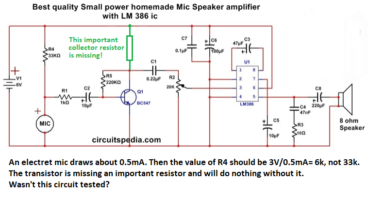
-
How to make Audio power Amplifier Circuit
audioguru replied to Aman bharti's topic in Electronic Projects Design/Ideas
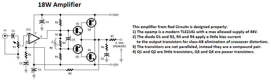
I am showing a CORRECTED audio amplifier circuit and a CORRECTED simple inverter circuit:
-
How to make Audio power Amplifier Circuit
audioguru replied to Aman bharti's topic in Electronic Projects Design/Ideas
The circuit shown is a block diagram, not a schematic. The inputs and outputs of the opamps are not shown and the collectors, emitters and bases of the transistors are not shown. An important capacitor between the positive and negative power supply pins of the IC is missing. Diodes or a transistor to bias the output transistors into class-AB is also missing then there is severe crossover distortion. The volume control is wired backwards and shorts the signal source. The transistors are not connected as a Darlington, they are simply paralleled, why? Hey, the amplifier has no specifications about its output power or distortion, the impedance of the speaker is also missing. The datasheet for the RC4558 by Texas Instruments recommends a maximum supply of plus and minus 15V then why does this circuit have supply voltages that are twice too high? With a plus and minus 15V supply, the maximum output voltage swing of the opamps is plus and minus 12.5V and the output transistors reduce the amplifier output to plus and minus 11V which is 7.8V RMS. Then the output power is only 7.6W into 8 ohms or about 13.7W into 4 ohms. I made a proper schematic of this nightmare of an audio amplifier showing everything wrong with it: EDIT: The same website Circuitspedia has an inverter circuit that is also completely wrong.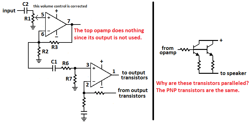
-
The original old Greek kit used TL081 opamps that have a problem called "Opamp Phase Inversion" where the output goes positively as high as it can if an input voltage gets within a few volts from its negative supply voltage. The improved project used newer opamps that do not have this problem. When the power supply is turned off then the huge positive filter capacitor for the rectifiers takes time to discharge but the low current negative supply capacitor discharges quickly. Then the output of this power supply project will have opamp U2 to force the output of the project to go positively as high as it can which will probably destroy whatever you were powering with it. The resistors on the base of Q1 detect that the negative supply voltage is dropping and causes it to conduct and short the output of opamp U2 to 0V so that it cannot cause the output of the power supply to go positively as high as it can. The circuit does not have a huge high current diode at its output to block a negative high current at its output from damaging it. A huge high current diode might be too slow to protect against damage.