ikrananka
-
Posts
8 -
Joined
-
Last visited
ikrananka's Achievements
")
Newbie (1/14)
0
Reputation
-
Sonos ZP-100 Custom Robinette Box for Headphones
ikrananka replied to ikrananka's topic in Electronic Projects Design/Ideas
Well I finally managed to get all of the parts I needed and have been testing out various configurations. Unfortunately, I am having a major issue with audible hiss, that I have been so far unable to resolve, and is even present when there is no music playing. My initial configuration was with the resistor network set at 12.4dB attenuation. The hiss was clearly present and so I moved to an 18.3dB attenuation resistor network but found that if anything the hiss was now louder. This may have been my imagination but I am certain that the volume of the music was also louder at the same output level compared to the 12.4dB attenuation. I also completely bypassed the resistor network (but still keeping the two R5 resistors in the circuit on the common ground), and found there was little or no difference to the two attenuated configurations. The only avenue I was thinking I might explore would be to buy some wide range potentiometers so that I can really ramp up the attenuation to see if that will make a difference. Of note is that the Sonos amplifier is a relatively modern (2005) solid state system that can output 50W per when the connected impedance is 8 ohm but can go up to 100W when the connected impedance is 4 ohm. So, could it be that the resistor networks I have been testing have simply been overridden by an automatic increase in output from the amplifier due to the perceived change in connected impedance? Really appreciate any suggestions on a way forward with this. -
Sonos ZP-100 Custom Robinette Box for Headphones
ikrananka replied to ikrananka's topic in Electronic Projects Design/Ideas
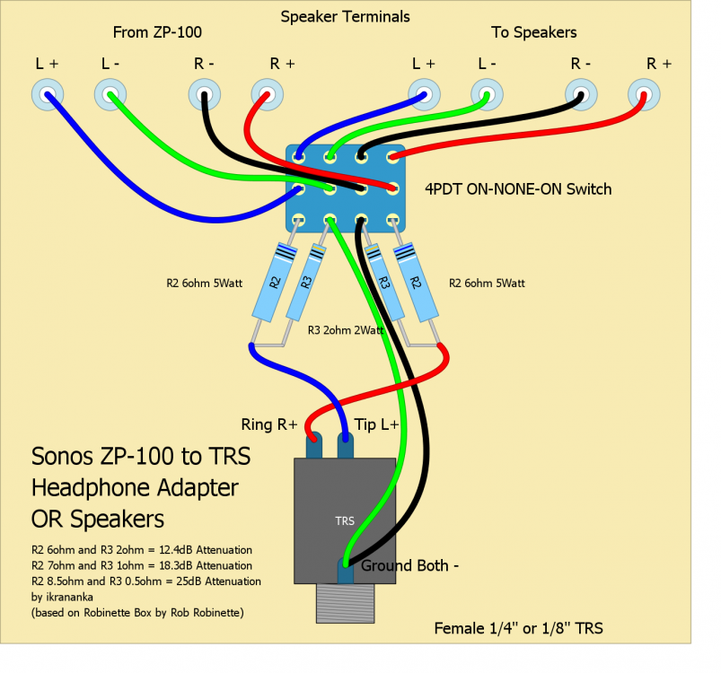
The ZP-100 is a legacy product and is a standalone amp that one connects your own speakers to. In my case a pair of bookshelf Klipsch Reference speakers. Trueplay only applies to Sonos's own amplified speaker lineup, i.e. PLAY:1, PLAY:3 and PLAY:5. I did make a mistake with the grounding. I forgot to test the ZP-100 and have confirmed that the speaker outputs are balanced and not single-ended. My diagram above would only work if the amp was single-ended. So, I have now added a couple of resistors to the negative outputs as suggested by Rob Robinette on his website. New diagram below.
-
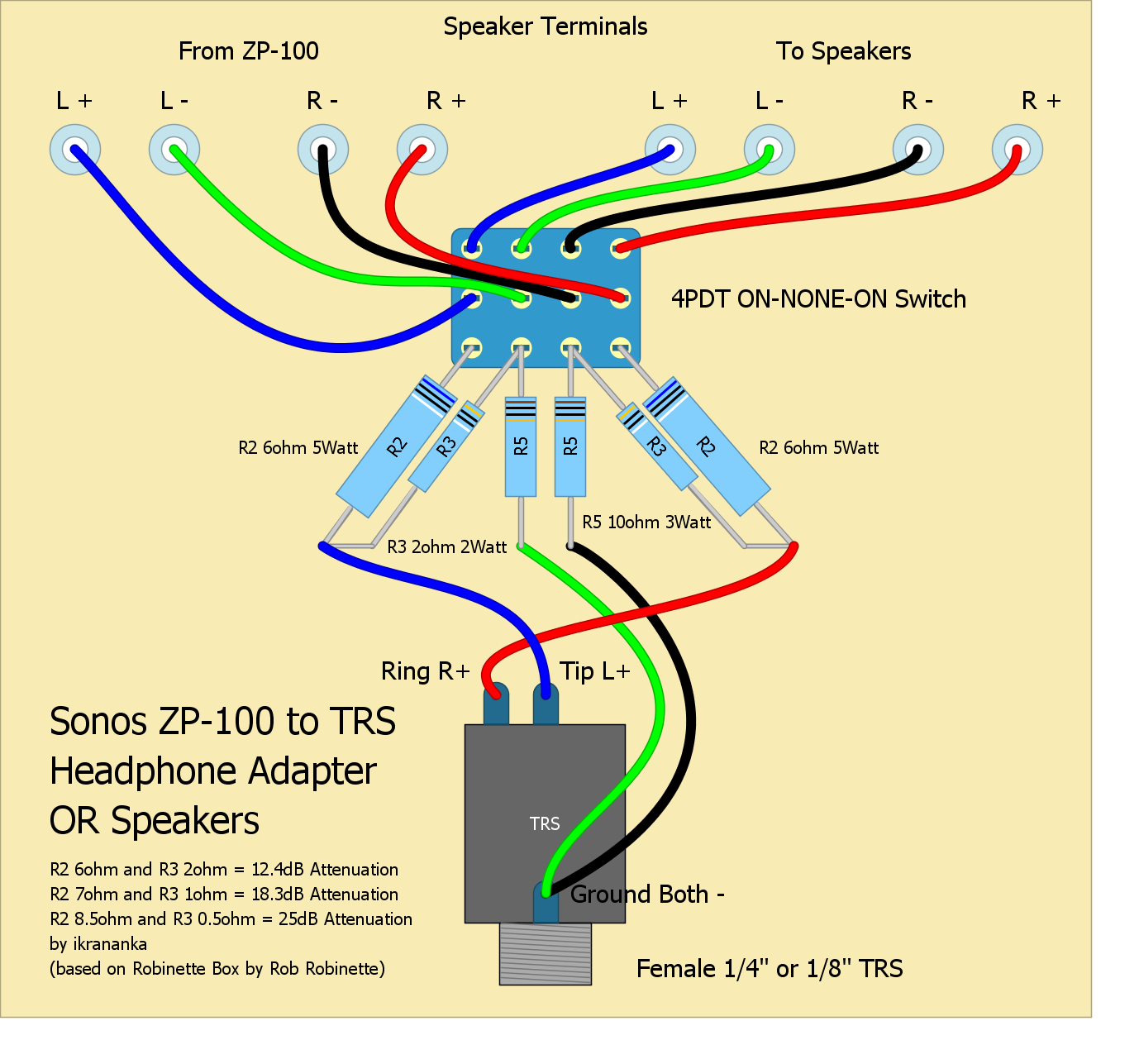
I'm trying to put together a custom Robinette Box that will allow me to use headphones with my Sonos ZP-100 units. Sonos made the bizarre design decision to not put headphone jacks onto these units. I'm buying my wife a decent set of headphones for Christmas but now need to build an adapter box that will allow her to use them with our ZP-100 units.I'm basing my design on a basic Robinette Box design but with a 4PDT switch that allows the speaker output from the amplifier to be either routed to our main speakers OR the headphones. I have put together a diagram of my proposed setup below. I'm certainly no expert in these matters and so would greatly appreciate ANY constructive comments on what I'm proposing. Any pitfalls I should be aware of?
-
The datasheet makes absolutely no reference to a ground connection. I emailed the manufacturer weeks ago but received no reply. I alos spoke to Mouser tech support - not much use either to be honest as the tech just looked at the datasheet and had no other info.
-
Is there an easy way to tell or do I need to try and follow the traces?
-
eBay's a great source, also Kijiji can be quite successful to pick one up locally. If you're keen then also check out the most active ColecoVision forums over at http://www.atariage.com/forums/forum/115-colecovision-adam/. There is also an active homebrew scene with some fantastic games being produced, e.g. http://www.opcodegames.com/ and http://www.colecovision.dk/collectorvision.htm.
-
I am in the process of building an internal power supply mod for the 1980s ColecoVision games console. This is based on an open frame power supply with triple output (http://www.cincon.com/data/products/cfm2_1/CFM40D_T.pdf). I have built and tested a prototype unit and it works great, is much lighter than the standard external CV power brick and has the advantage of only requiring a standard household power cord to connect the CV to the mains supply. However, I am not an electrical engineer and have concerns over safety and grounding but do not know the answers. So, looking for some advice on the following (hope someone can help): 1.In one corner of the power supply PCB there is an earth/ground symbol marked with a trace running from a capacitor to a circular trace running around the adjacent mounting hole. I believe that I should have this connected to ground - is this correct? 2.One of the other mounting holes also has a circular trace running around it (connected to another capacitor) but does not have an earth/ground symbol next to it. There is NO electrical connection between the two circular traces - should this second trace also be grounded? 3.The other two mounting holes do NOT have traces around them. Nevertheless, I plan on mounting the power supply using metal screws and metal standoffs. The bottom screws will be outside of the CV case, can be touched, and so in theory there could be an internal short to these screws - do you agree therefore that all four screws/standoffs be grounded? 4.Do I need to provide some kind of physical shield in case a user pokes a metal objects through the CV air vents thus preventing them from touching the power supply? Or is this overkill? I can see quite a number of consumer electronic items that I have that I could easily poke something inside and touch the internals (not that I ever would mind you).