CBETO3AP
-
Posts
22 -
Joined
-
Last visited
CBETO3AP's Achievements
")
Newbie (1/14)
1
Reputation
-

0-30 VDC Stabilized Power Supply 0.002-3 A
CBETO3AP replied to CBETO3AP's topic in Power Electronics
-
0-30 VDC Stabilized Power Supply 0.002-3 A
CBETO3AP replied to CBETO3AP's topic in Power Electronics
woala
-
 OZ6YM reacted to a post in a topic:
0-30 VDC Stabilized Power Supply 0.002-3 A
OZ6YM reacted to a post in a topic:
0-30 VDC Stabilized Power Supply 0.002-3 A
-
0-30 VDC Stabilized Power Supply 0.002-3 A
CBETO3AP replied to CBETO3AP's topic in Power Electronics
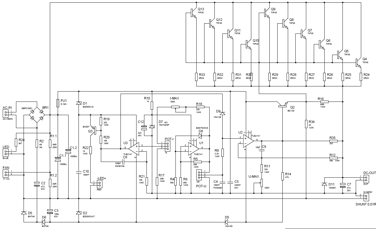
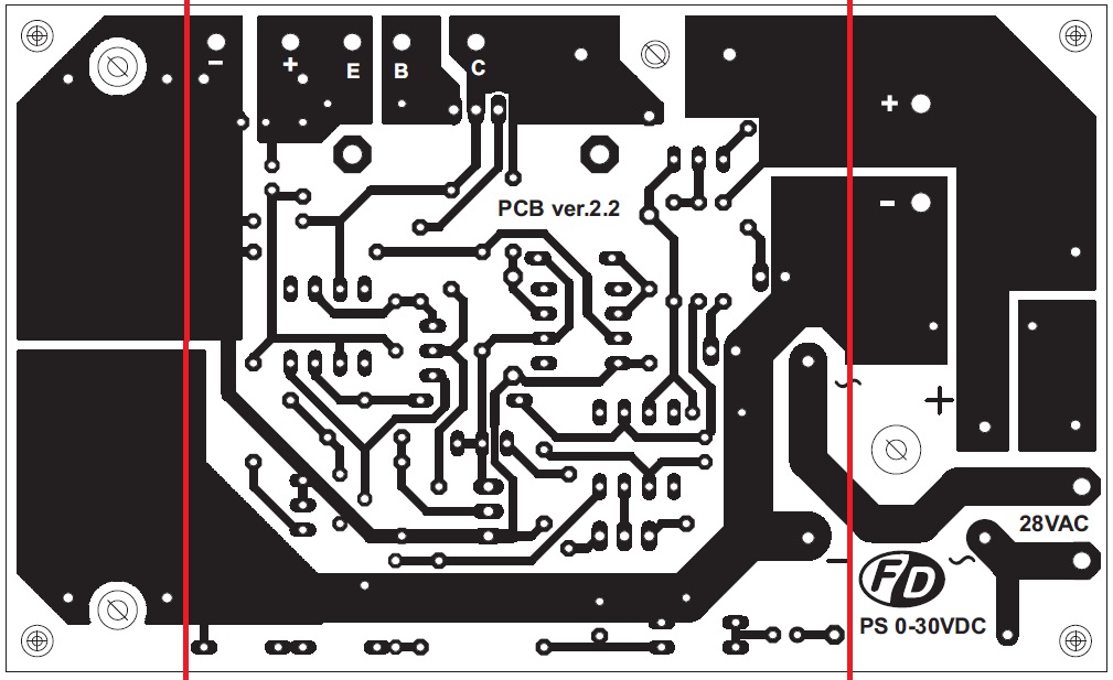
Hi I work on Hristo PCB, member of this community. http://diyfan.blogspot.com.es/2012/02/adjustable-lab-power-supply.html By changing the shunt, as I feared, the current regulation is very slow, now I'm looking solution without increasing the shunt. No load through the PCB and is cut so.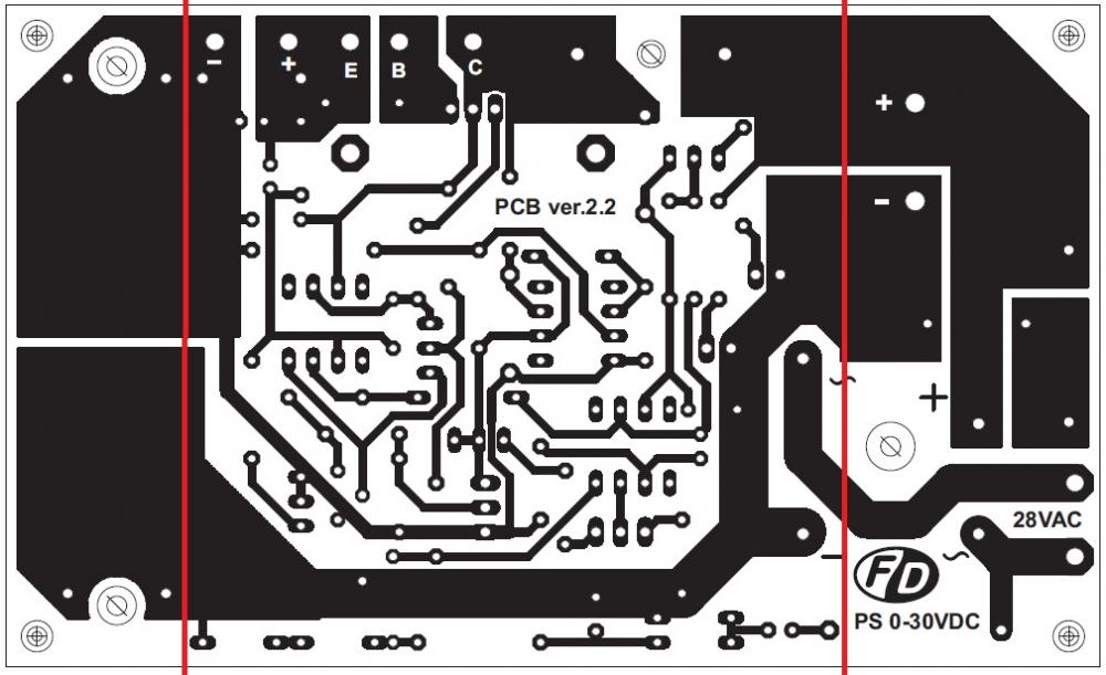
-
0-30 VDC Stabilized Power Supply 0.002-3 A
CBETO3AP replied to CBETO3AP's topic in Power Electronics
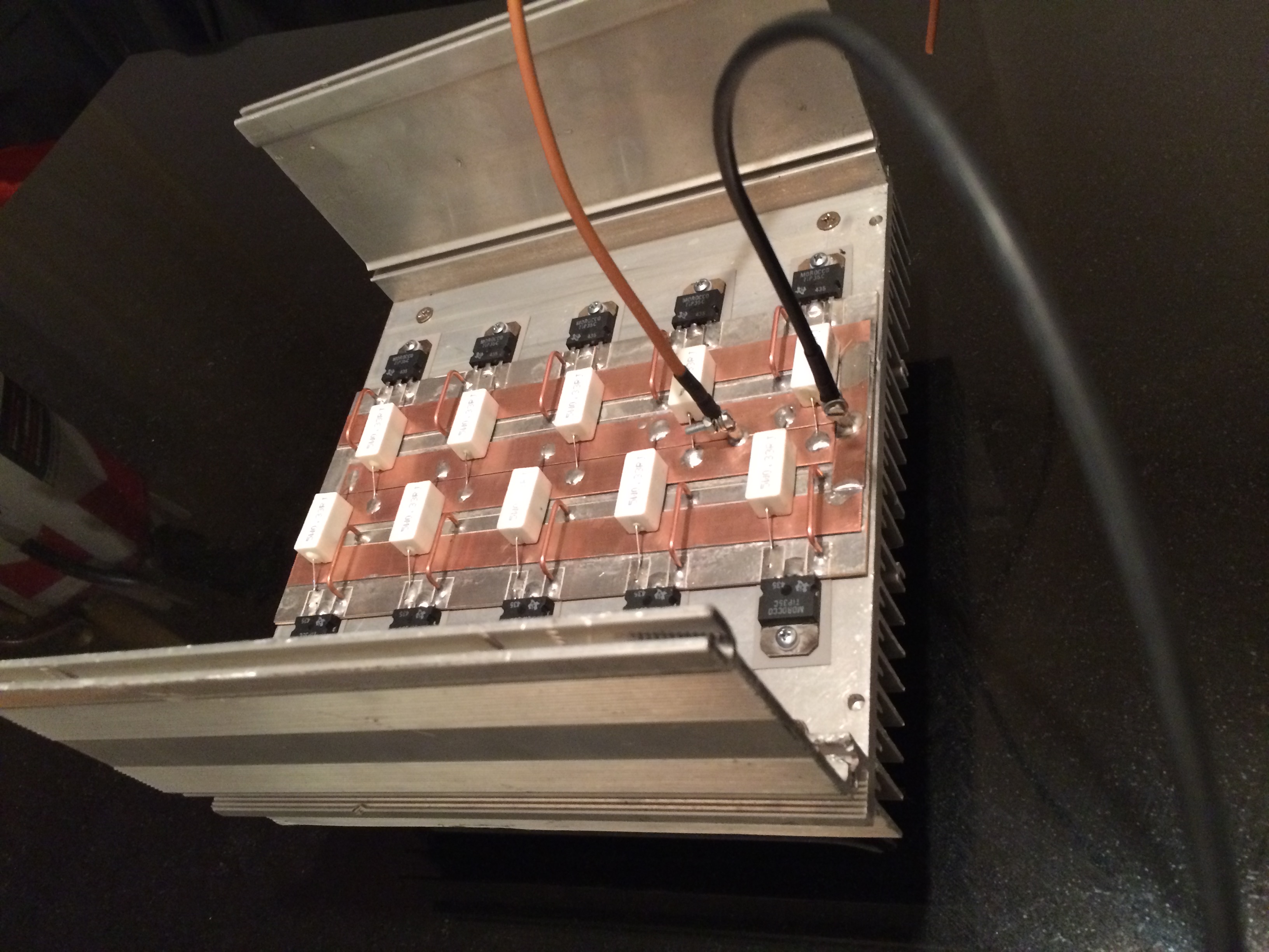
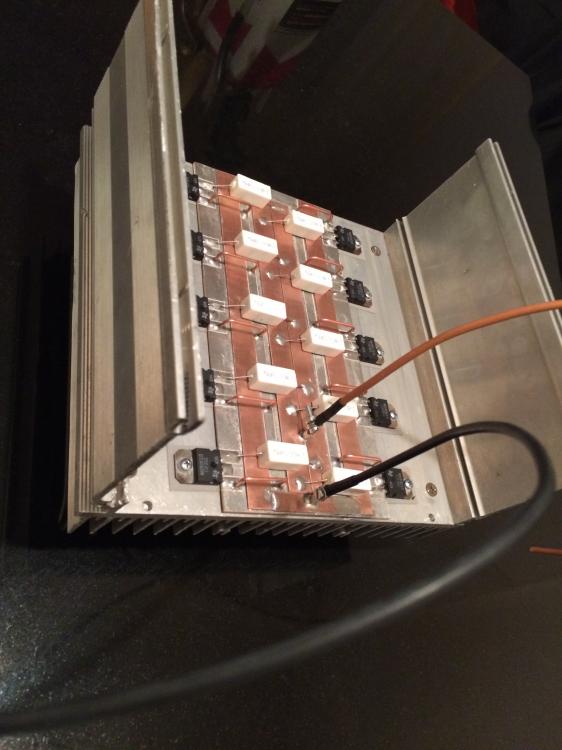
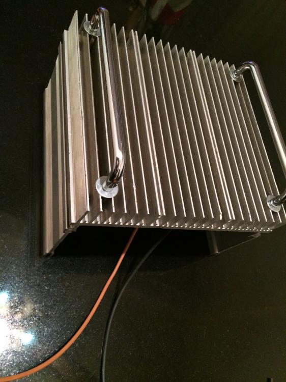
Yes, I have been forced to change the shunt resistor. Now this place metal shunt 10A / 0.1V.Thus I am saving me 1.4V. Plus something like 0.5V to have 10 emiter resistor in parallel. Low Vdrop is because the shunt is bolted directly to the output. And the sensing cable to the out. -
0-30 VDC Stabilized Power Supply 0.002-3 A
CBETO3AP replied to CBETO3AP's topic in Power Electronics
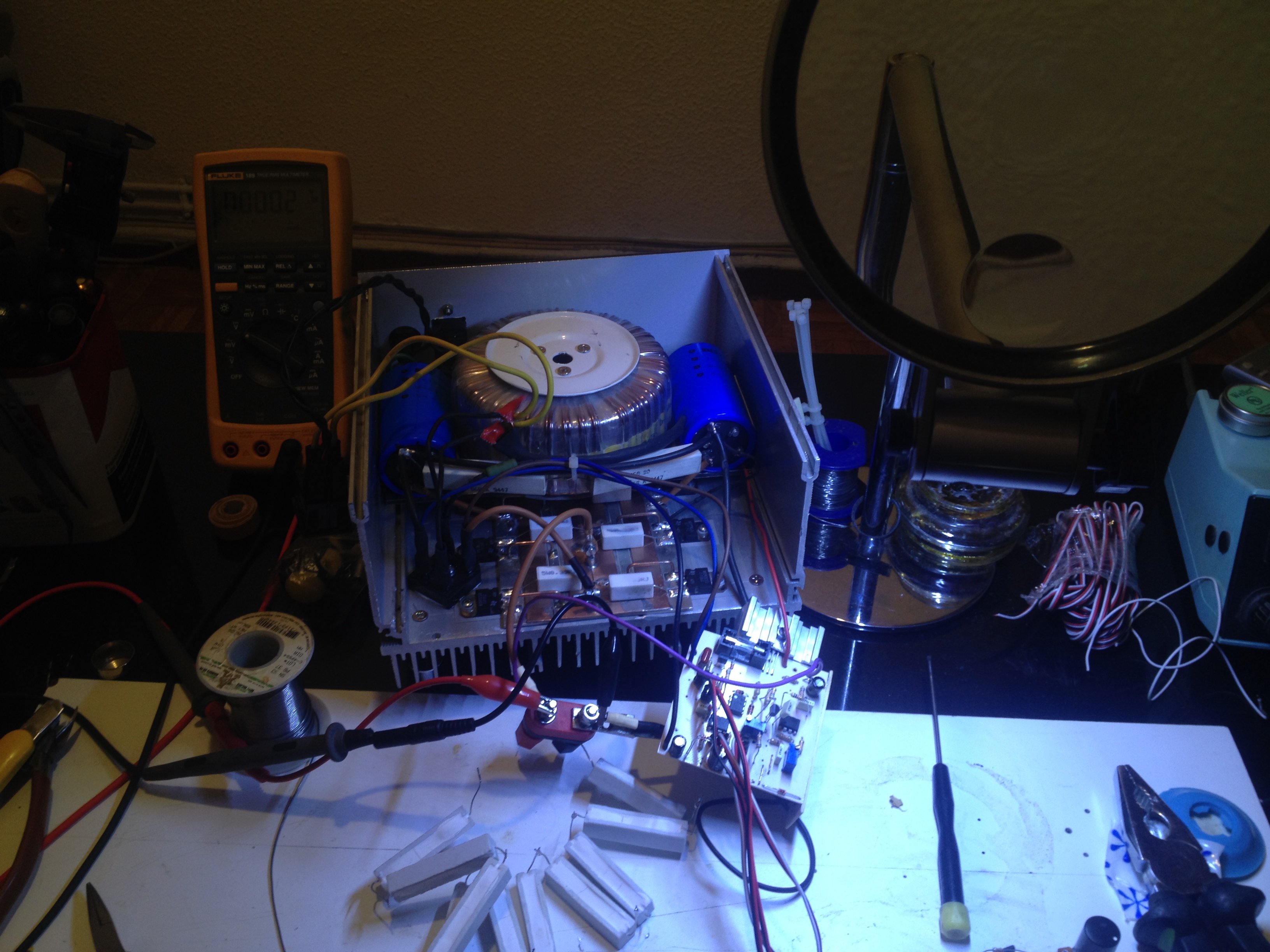
measured24V/11A - 0.003V drop, for now
-
0-30 VDC Stabilized Power Supply 0.002-3 A
CBETO3AP replied to CBETO3AP's topic in Power Electronics
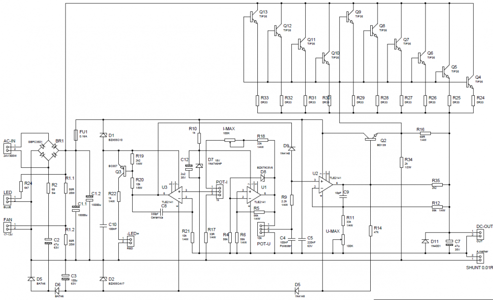
BD140 driver emiter current tested - 85mA max at 10A load (200mA expected) The peak voltage of this toroid transformer (filtered, no load) - 38v, i modifed the secondary from 12v/25A to 24V/12.5A 741 opamps is on negative -5.6V (4.7V in my case) supply, ofcorce The LM311 is a comparator I know, will see... "Then you must buy a few hundred transistors, test their gain and use only the best ones" I usually buy scrap and test "Maybe you calculated with "typical" current gain" nop, i calculate well and have some luck with the gain -
0-30 VDC Stabilized Power Supply 0.002-3 A
CBETO3AP replied to CBETO3AP's topic in Power Electronics
Limited by the 24V / 300W transformer this will give out 24 or 20V-10A. I bought fake China MC34071 and now I'm doing tests with UA741, the truth is that there are going pretty well. I expect a TLE2141AIP and if it is the original'll ask the rest. What I will possibly do after testing is remaking the scheme to put LM311, open collector 50V out at currents as 50mA. This and a more powerful transformer allow me more output. The use of such power is for example the CNC machine cutting expanded polystyrene with hot wire. p.p. By my calculations with 1 or 2 driver transistors BD140 is enough. LM311-n.pdf -
0-30 VDC Stabilized Power Supply 0.002-3 A
CBETO3AP replied to CBETO3AP's topic in Power Electronics
-
0-30 VDC Stabilized Power Supply 0.002-3 A
CBETO3AP replied to CBETO3AP's topic in Power Electronics
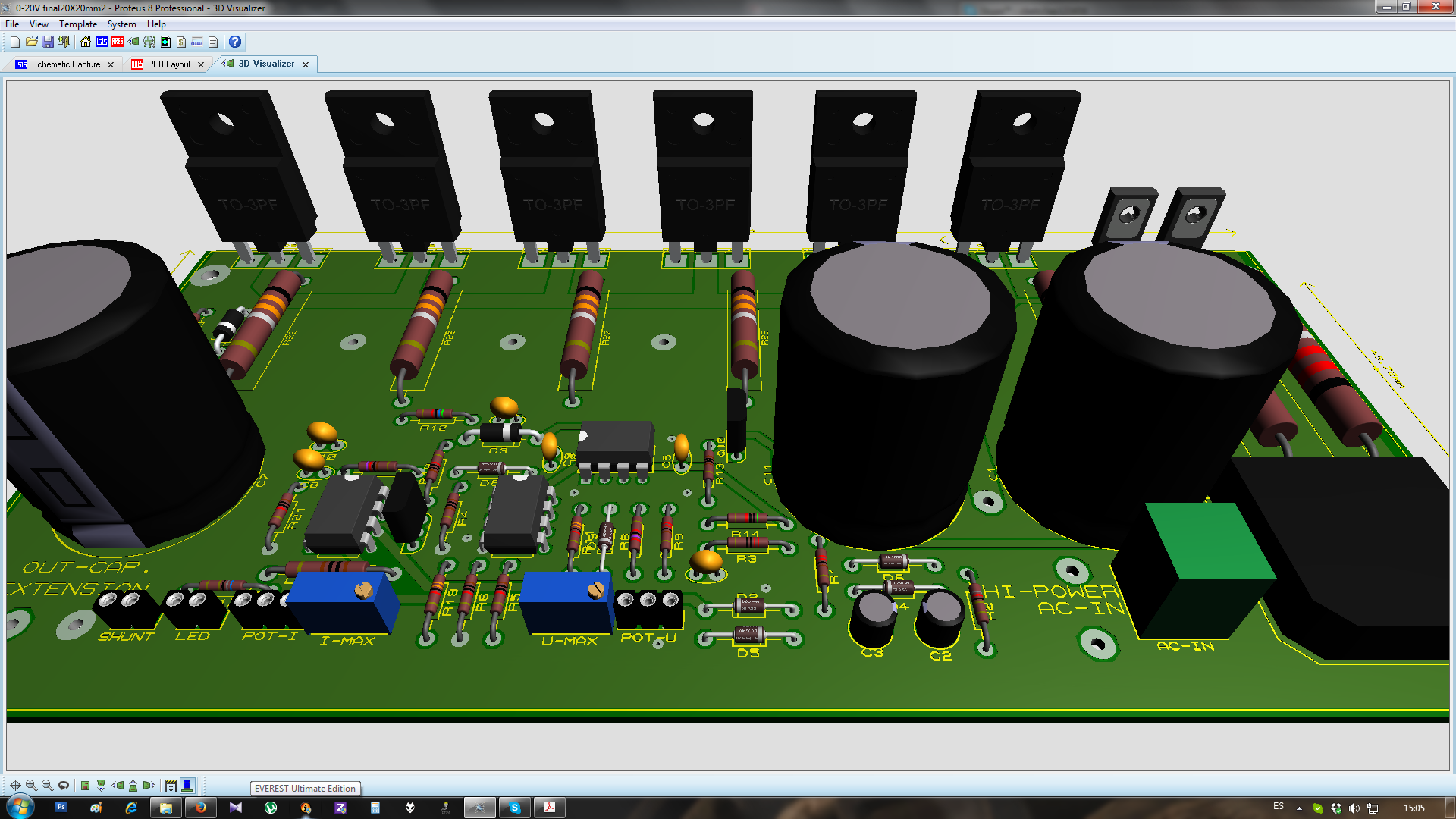
Thank you. At the moment he stays. I have some progress with Proteus.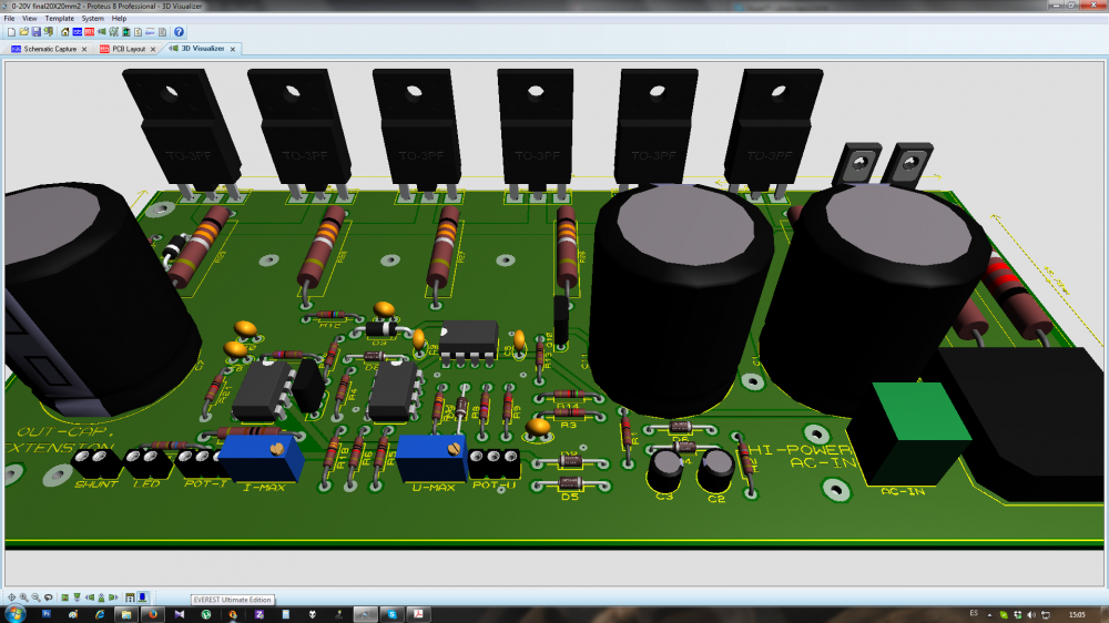
-
0-30 VDC Stabilized Power Supply 0.002-3 A
CBETO3AP replied to CBETO3AP's topic in Power Electronics
I have a doubt. What is the function of zener D1 (D3) of 10v, why is there? -
CBETO3AP reacted to a post in a topic:
0-30 VDC Stabilized Power Supply 0.002-3 A
-
0-30 VDC Stabilized Power Supply 0.002-3 A
CBETO3AP replied to CBETO3AP's topic in Power Electronics
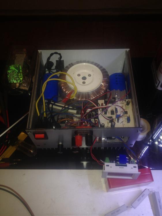
First thanks for the comments. Just I get started to modify the scheme and did not have much time to review and change everything I need. Also I expect your comments. It is the first time I use Proteus. I always try to build recycling scrap, bought mainly old PCB 1 € / 1kg. The TIP35C have them in large quantities, with pin collector cut but not be a problem. The toroid transformer is 2x12v / 300w, C1 will probably be 2x18000uf, my friend has 4 also scrap. So far I have not decided, we'll see. What I had not thought is the reverse bias of BD140, I'll have to protect it, thanks for advice. BD139 is 12W 1.5A, TIP35C gain to 1.5A is 25-50. If consumed 10A output to 0V, in the collector BD135 would have 0.4A for 30Vce = 12W. I'm wrong? I know, it is at the limit... You can suggest another transistor to facilitate me? Why R7 is the wrong value for this configuration??? TIP35C.pdf BD140.pdf BD139.pdf 0-20v,0-10a1.bmp 0-20v,0-10a1.bmp -
0-30 VDC Stabilized Power Supply 0.002-3 A
CBETO3AP replied to CBETO3AP's topic in Power Electronics
0-20v,0-10a.bmp -
0-30 VDC Stabilized Power Supply 0.002-3 A
CBETO3AP replied to CBETO3AP's topic in Power Electronics
Hi audioguru. Now that I'm done with the other conversation I would like to continue this. To me the truth I do not like to limit the transistor with a resistor if possible. You do not think it is possible to hold without burning? From what I see in the manufacturer PDF, gain low wen collector current up. I would try immediately if possible, but for now have only the PCB, I hope the components, and am content with theory. Please excuse my bad English, it is the google translator.. -
0-18V Pos/Neg 1A Current Limited
CBETO3AP replied to liquibyte's topic in Electronic Projects Design/Ideas
The truth is that I respond with fear, you're very reluctant to my comments and I need not bother you. For me it is obvious that feedback must be in the output of the circuit. I suspected but was not so obvious that the C11, C12 are very large but audioguro corrected me and then I saw that could cause the problem. You need to know the why of each component in your circuit to reason and improve it. This is sometimes quite difficult, especially when you copied the outline of another without understanding. I'm not electronics guru, so I entered this community, to continue to learn from those who know more. Here I ended the conversation with you, you obviously do not need my help. -
0-18V Pos/Neg 1A Current Limited
CBETO3AP replied to liquibyte's topic in Electronic Projects Design/Ideas
If I'm wrong about something (of course this can be and prefer to see in the community), there is audioguru, who always find the error and tell, and always right, which I respect a lot. This is already on frame of contecst so I would like to haver not said anything about your "work of art". Practically not get anything more than what can be done with the LM317, LM337. In fact you've gotten worse stability, thereby constructively we have discussed before. I will not bother to draw a circuit totally different from yours, it's easier to grab any circulating on the internet and we would have the same result as minimum. Everything I've said has been with good intentions, so far. I am sorry that you've had that bad.