ElectronMan1
-
Posts
7 -
Joined
-
Last visited
ElectronMan1's Achievements
")
Newbie (1/14)
0
Reputation
-
Hi there! I think this new product called Batteriser is a bunch of marketing hype and won't stand up to any real tests. I would not recommend anyone purchase this product and instead wait for the reviews to come out and to be very skeptical It's a stainless steel sleeve that goes over a battery and has a micro DC booster to step up the voltage to 1.5V to "get 80% more out of battery" - they used to say 800% longer Their website http://batteriser.com/ I try to keep an open mind and interested in any thoughts people may have. Dave Jones over at the EEVblog did a debunking https://www.youtube.com/watch?v=4iEshd6izgk My thoughts: No battery level monitor or low battery warning would be very annoyingCan it really keep up with the high current drain, can it really handle several amps?Shorting risk, would not want to be shorting out D cells with these thingsBattery leakage risk due to over-dischargeCannot use with rechargeable batteries due to over-discharge reasonsCompany is dodgy as, very shady testing methods. They said 1.4V - 1.35V for normal battery is considered "dead".. gimme a breakThere is only maybe 10% of battery capacity left at 1.1V, and the boost converter will need to draw current from this 10% to operate and the efficiency will be terrible.. not worth itOne thing I don't know and would like to know is, would a product hit its "cut off voltage" and turn off if it dipped under that voltage of say 1.1V only for a moment? Say with a camera when it takes a flash and charges the capacity, there could be a voltage sag which takes it under 1.1V for a moment, but then would shoot back up. Would this Batteriser then be useful to stop this? With a new battery that voltage may only drop momentarily to 1.3V, but over time it drops to 1.1V for that very short period of time.. Interested in your thoughts!
-
Ideas for Single AA and AAA batteries?
ElectronMan1 replied to ElectronMan1's topic in Electronics chit chat
Thanks, that puts things in perspective - I checked out the datasheet of Energiser AAA and even if I only want 100mA at 5V (0.5W) and I draw 400mA-500mA at an average of 1.25V to get there, my mAh capacity of the AAA would only be around 450mA in total as per datasheet capacity discharge curve. That's a huge drop, as it could be as high as 1100mAh at 25mA, and 900mAh at 100mA. I think it could be fun to build a joule thief and use it as a little night light though -
Ideas for Single AA and AAA batteries?
ElectronMan1 replied to ElectronMan1's topic in Electronics chit chat
Thanks, wow I'm going to check out the MAX8815A datasheet. If I can get 500mA from a AAA battery @ 5V that'd be awesome -
Hi, I have some AA and AAA batteries lying around and looking for some ways to use them. Like when you buy a 4 pack of batteries, and the product only needs 3. What to do with the left over one?? I try not to mix batteries so I'm looking for some ideas on how to use them. Some ideas like a single AAA flashlight, maybe a clock? Any other ideas? I bought a 0.9V-5V DC-DC boost converter but it sucked, could not deliver even 50-100mA without large drop in output voltage Also is it really a big deal if I mix two brands of Alkaline batteries, with similar levels of charge??
-
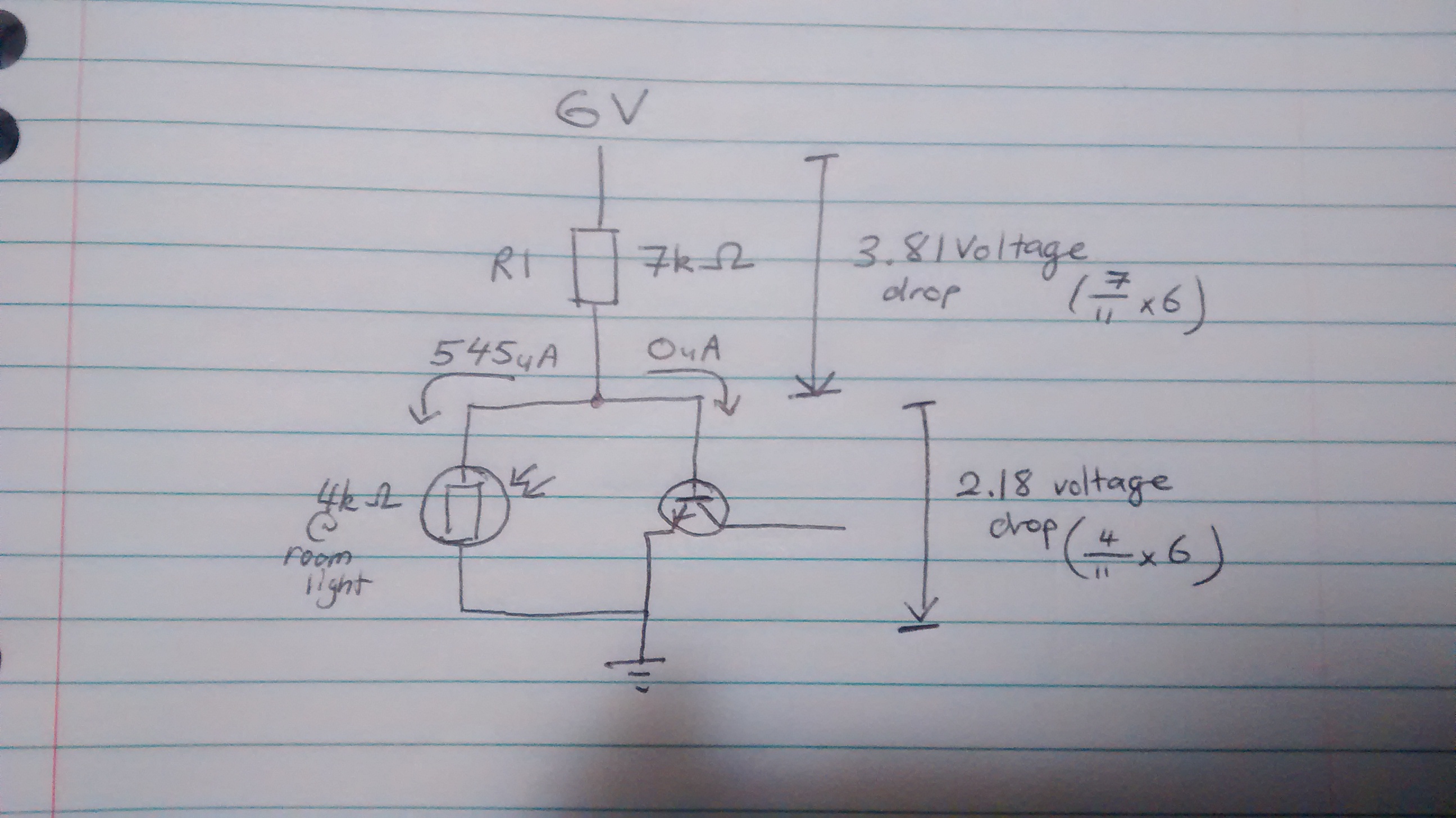
Ah hah. I see the problem, the LDR is too high at 4k to divert enough current to ground. The transistor requires too much base current to fully saturate and has too wide a 'window' in which it will operate but not saturate. Time to research an appropriate Darlington transistor. Thank you
-
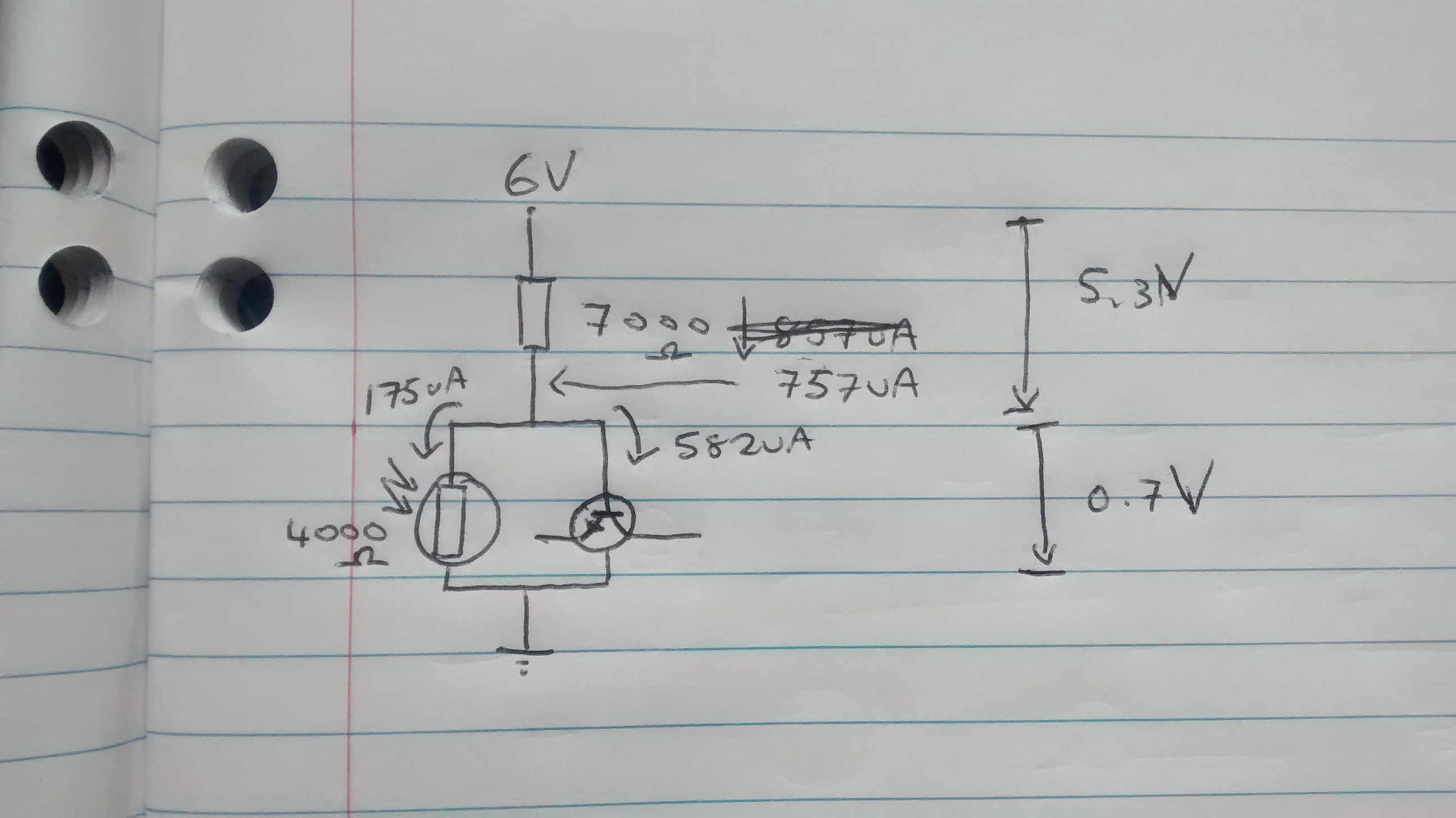
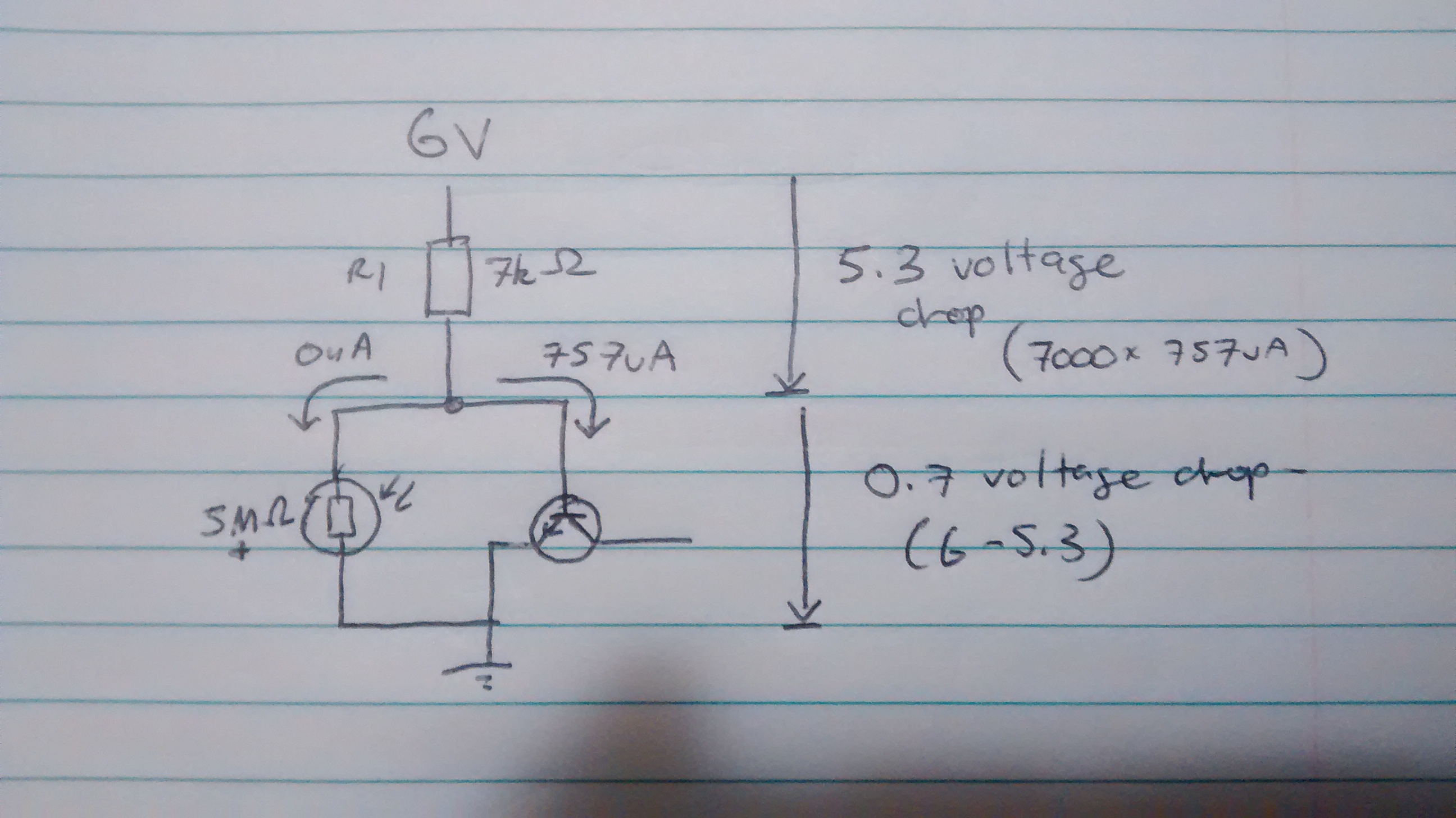
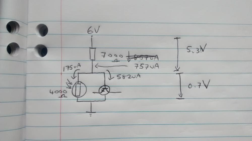
Thank you audioguru. Did you derive the saturation current ratio of 1/20 from the "Conditions - Base-Emitter Saturation Voltage" - collector current 10mA and base current 0.5mA from the datasheet? I think I understand your calculations, I have redrawn to confirm that I understand you correctly. I would like to explore the Darlington transistor - or two BC548 arranged into a Darlington pair.
-
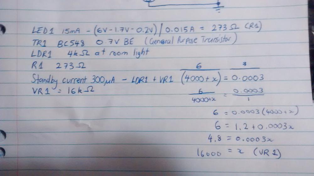
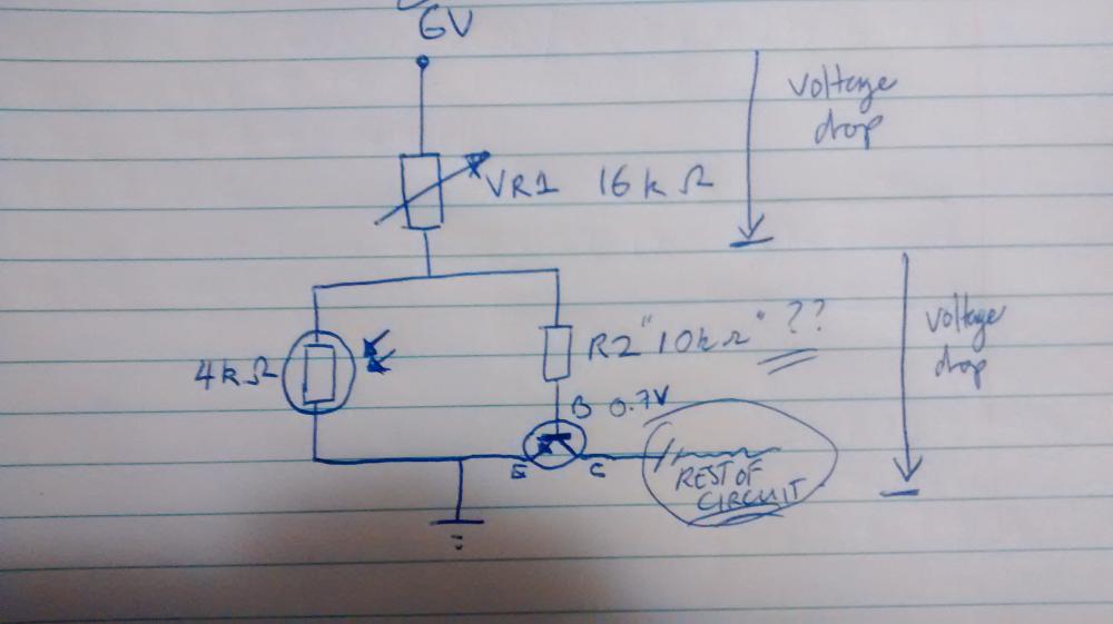
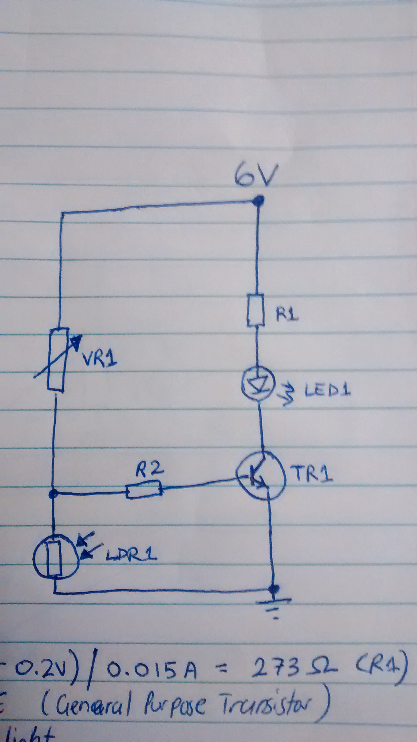
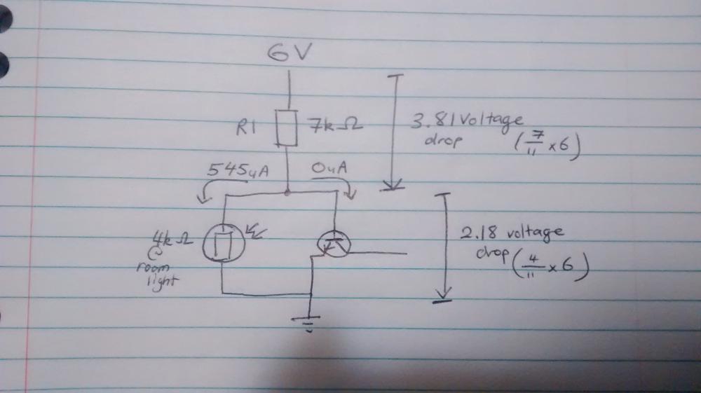
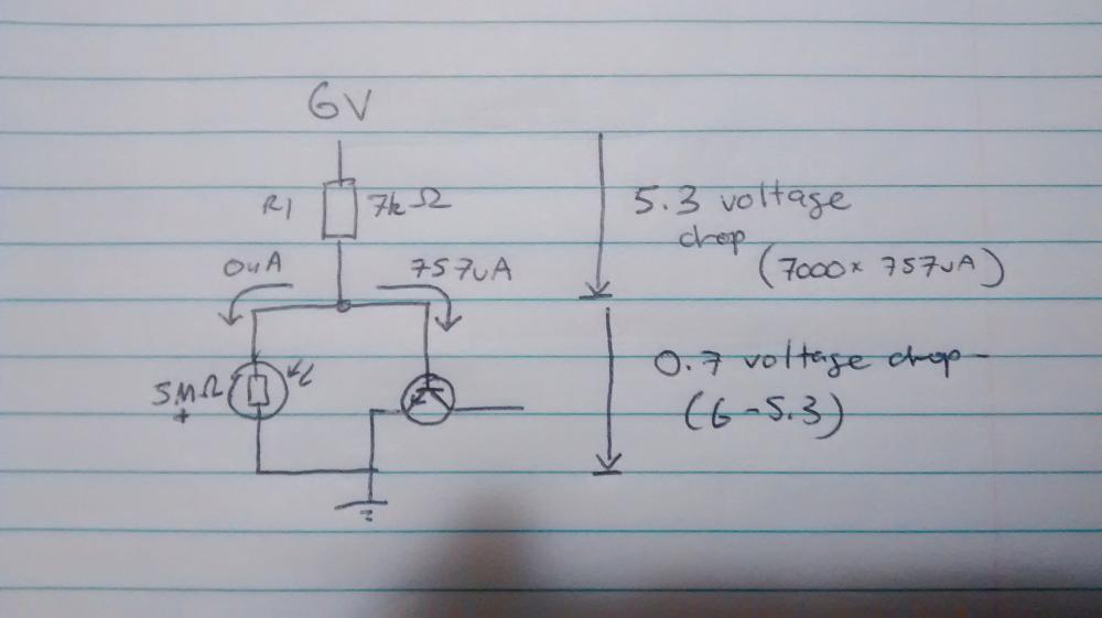
Hi, This will sound like a homework question. All I can say is that it isn't, and I'm not looking for any answers so I can pass any tests (those days are behind me, I hope!) For those interested I'm an IT professional dabbling in electronics. I am designing this Dark Activated Light for fun and I'm having a problem understanding how to calculate the value of the resistor that goes into the Base of the Transistor. The item is R2 (as below). Some calculations below I just made up a figure of 300uA, seemed small enough not to waste battery but large enough to turn on the transistor. This is the part I am struggling with: How do I calculate the value of R2, to give the right voltage drop of 0.7V when the LDR has a higher resistance. I tried blocking off the 4k (say when dark) and focus on the VR1 + R2 path to give 0.7V -> 6V - 0.7V = 5.3V -> 5.3V / 200uA = 26500 ohms. I have 16000 ohms above, so I have about 10000 ohms which I plugged in to make up 26000-ish ohms. However wouldn't this always switch on the transistor as the voltage drop across the parallel path will be equal? I calculated the current through this leg of the circuit, determined the ESR to be 2857 ohms for the 4k || 10k part, which was 318uA. The LDR leg had 227uA and the Base of the transistor 91uA. I checked the BC548 data sheet but couldn't find if it's enough current to switch on the transistor.. just the voltages. https://www.fairchildsemi.com/datasheets/BC/BC547.pdf But am I on the right track, I just starve the Base of current so it can't turn on? Technically it has the voltage but not enough current.. ? Then when the LDR gives resistance it gets the full 318uA which is enough to switch it on? Also is this how electrical engineers do these calculations? Is there is a better way? I'm really just flying solo with these calculations, and you can probably tell