Stockleys
-
Posts
2 -
Joined
-
Last visited
Stockleys's Achievements
")
Newbie (1/14)
0
Reputation
-
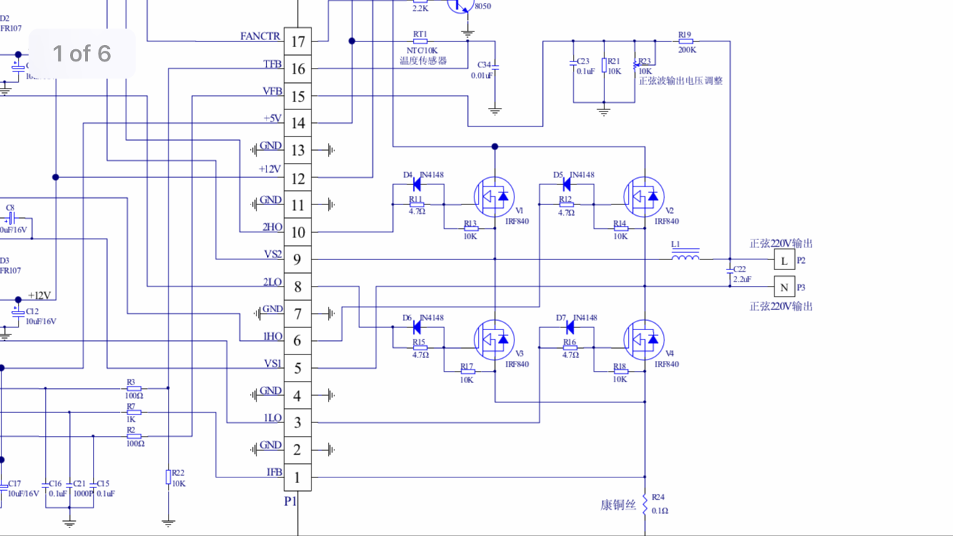
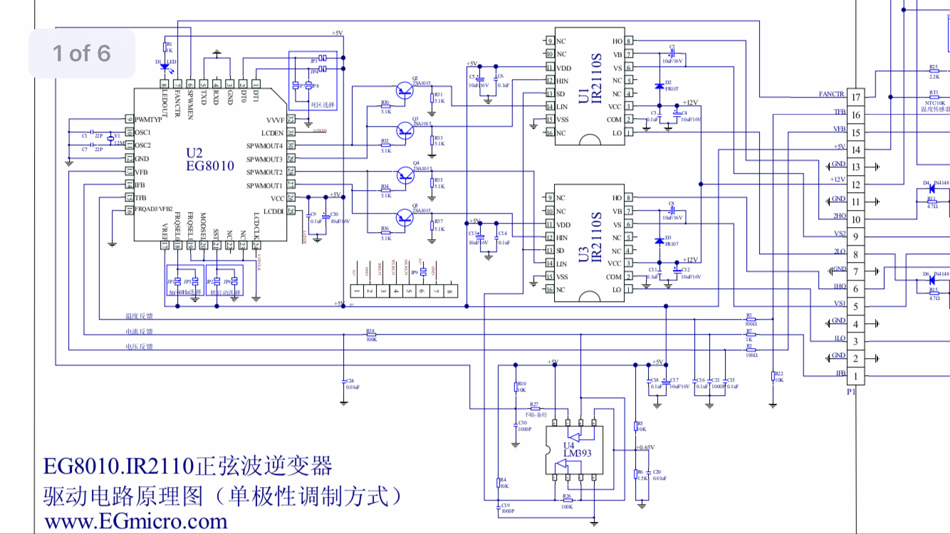
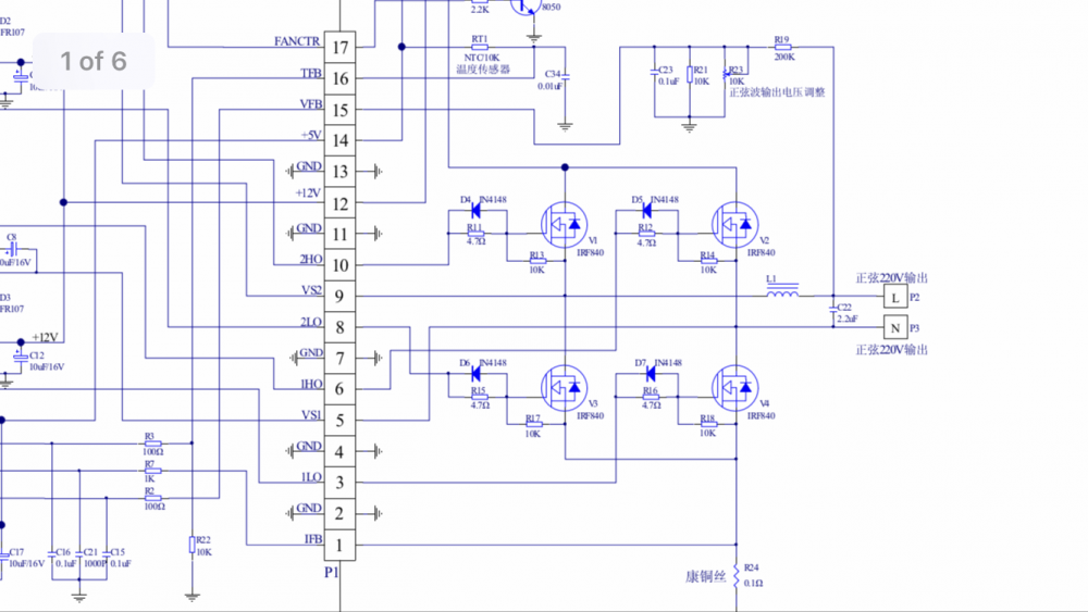
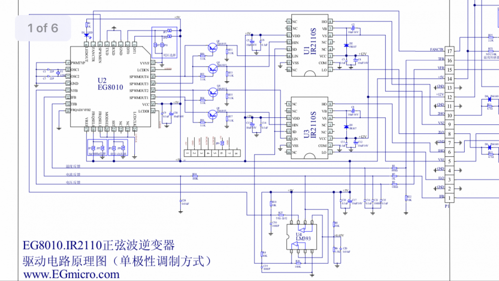
I got myself a usb scope. I found that the egs002 wasn’t giving the correct wave. On outputs 1 and 2. And output 3 was a constant 6v. Not a wave at all. Got another egs002 (before getting the scope). And that had one dead output. Attatched is a schematic for the egs002. And the h bridge. Which although not for my inverter, is identical
-
Hi all. First time post for meI’m after some helpI am trying to repair a high frequency 3000w inverter.It worked great for 3 weeks when I got it (after replacing 2 IGBT’s)But then they blew and many more replacementsI bought a new spwm board from the manufacturer and a complete new set of IGBT’s along with their associated resistors and diode.Installed. And nothing. ABout 10 seconds in and one of the h bridge drivers exploded.So I ordered an EGS002 board from amazon. All pinouts exactly the same. Same chips as the spwm from the manufacturer only a third the price.I have installed this and tested all components around it including the IGBT’s. They are all good.The IGBT’s are getting a steady 390vdc source. The spwm getting a steady 5v and 12vBut I can’t get an output. I can hear the transformers buzz for 3 seconds then stop I get a blip of up to 8vac at the output. The spwm board flashes out the code for under voltage and over voltage. Where do I go from here? I don’t own a scope. Only a ddm. I have checked and re check all components and solder joints. But as I don’t own a scope, I can’t think what else to do.Thanks in advance