Search the Community
Showing results for tags 'lm2575'.
Found 1 result
-
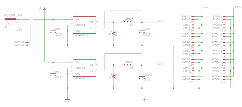
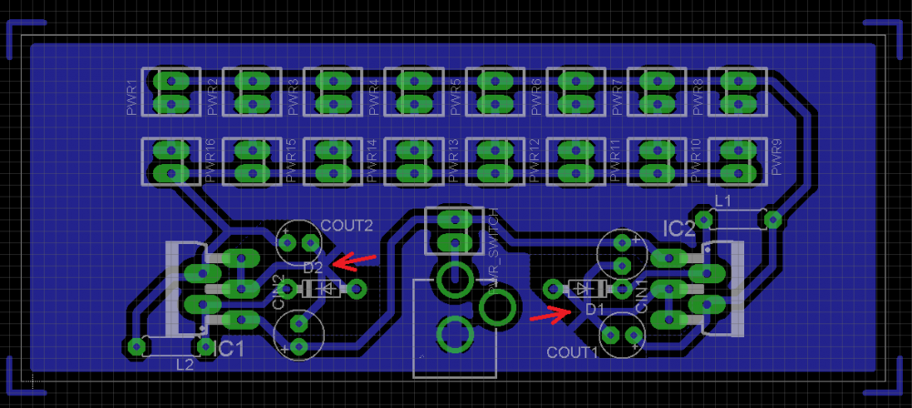
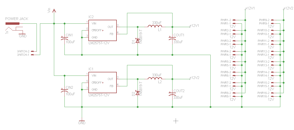
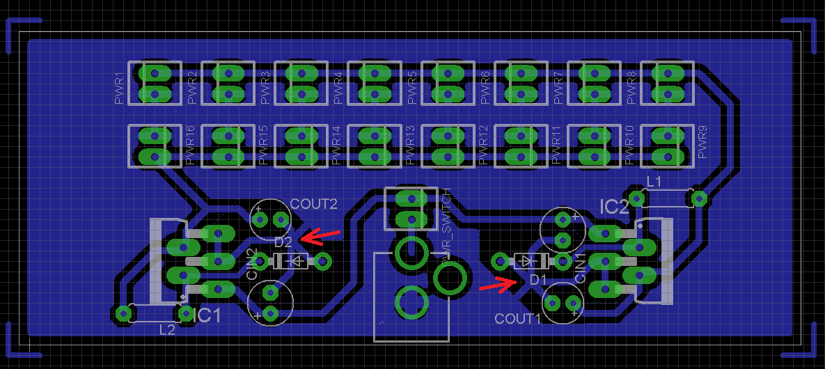
To replace my overheating linear regulator DC-DC converter, I've designed this new board. This time I used a couple of switching 12V regulators .Here's the data sheet for reference: http://www.kynix.com/uploadfiles/pdf9675/LM2575-12BN.pdf I'm using two 1 amp regulators because my local supplier doesn't have a 2 amp version. Here are the schematics. Here's the board: There are no pictures of the board because it doesn't exist yet. This time, I did the math first and didn't blindly built the thing. The red arrows highlight the single-point grounding I tried to make, as recommended in the datasheet. Is that design correct?. Here is my math for calculating the temperature rise from ambient temperature. According to the LM2575 datasheet, the power dissipation is calculated as follows: PowerDissipated=Vin.Iq+(Vo/Vin).Iload.Vsat Vo=12V,Vin=18V,Vsat=1.4V,Iq=10mA,Iload=1A PowerDissipated=0.18W+0.93W=1.11W Again, from the LM2575 datasheet, its termal resistance (junction to ambient, in worst case) is 65°C/W, which would keep the regulators just below 100°C considering a ambient temperature of 25°C. If I use my heatsinks with 20°C/W and the regulator thermal resistance (junction to case) of 2°, that would keep the regulators under 50°C My questions are: 1. Is my heat dissipation calculations correct? 2. Is my board designed correctly, especially regarding the required single-point grounding for the regulator pins? These points are marked by the red arrows on the board image.