Arduino Weather Station with DHT11 and BMP180
- Nick Koumaris
- https://educ8s.tv
- info@educ8s.tv
- 19.601 Views
- easy
- Tested
Introduction
In the previous tutorial I showed you how to build a weather station using only the DHT11 sensor and I said the readings from this sensor is fairly accurate. In this tutorial, I will be using the DHT11 to measure only the humidity and BMP180 to measure pressure and temperature. That’s because its readings are more accurate than the DHT11 temperature readings.
Project Parts
I will be adding only the BMP180 sensor to the list in the previous tutorial.
1. BMP180 barometric pressure/temperature sensor.
2. DHT11 temperature and humidity sensor.
3. 16×2 LCD keypad shield.
4. Arduino Mega.
5. Breadboard.
6. Jumper wires.
7. Resistors.
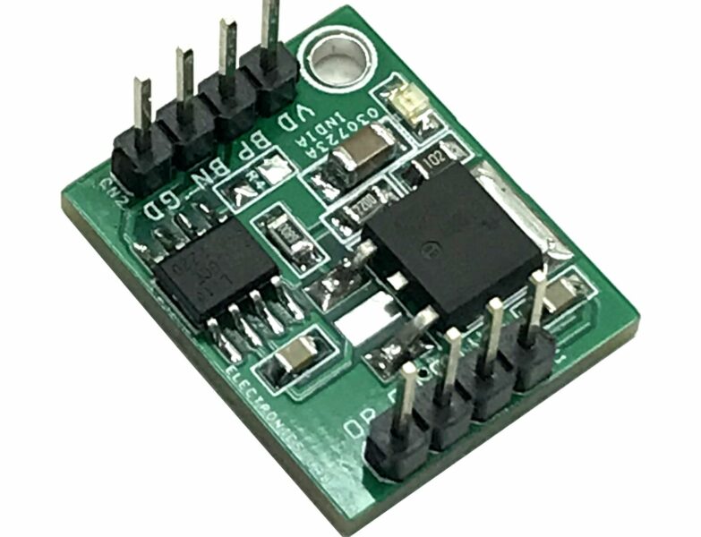
The BMP180 is the new digital barometric pressure sensor from Bosch Sensortec, with a very high performance and it uses the I2C (pronounced I-squared- C or I-two- C) protocol. This digital sensor can measure barometric pressure, temperature and altitude.
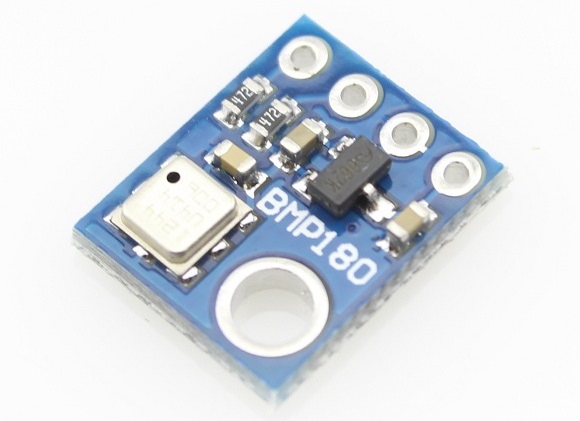
This sensor is a four pin device, the first pin is labelled VCC, second pin GND and the last two are the clock (SCL) and data (SDA) pins. You can purchase this sensor here.
The DHT11 is something we are familiar with, it has been used in couple of our tutorials here as a low cost temperature and humidity sensor that operates using the 1-wire protocol. It costs about $2 and you can get it here.
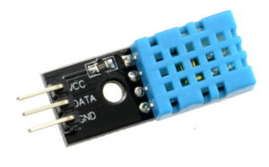
The readings from this sensor are fairly accurate, so we will be using this sensor to only measure humidity since the BMP180 gives more accurate temperature readings.
This sensor has three pins, the first which is the power pin VCC, next pin which is the middle one, which is the signal out or DATA pin and lastly the ground pin labelled GND.
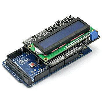
Yes, we will also be using the 16×2 LCD keypad shield as used in the previous tutorial. This shield makes connecting the 16×2 LCD module to any system quite easy, as it simply just plugs on the Arduino mega which is being used for this project. You can get this shield here.

Schematics
Wire up your component as shown in the image below.
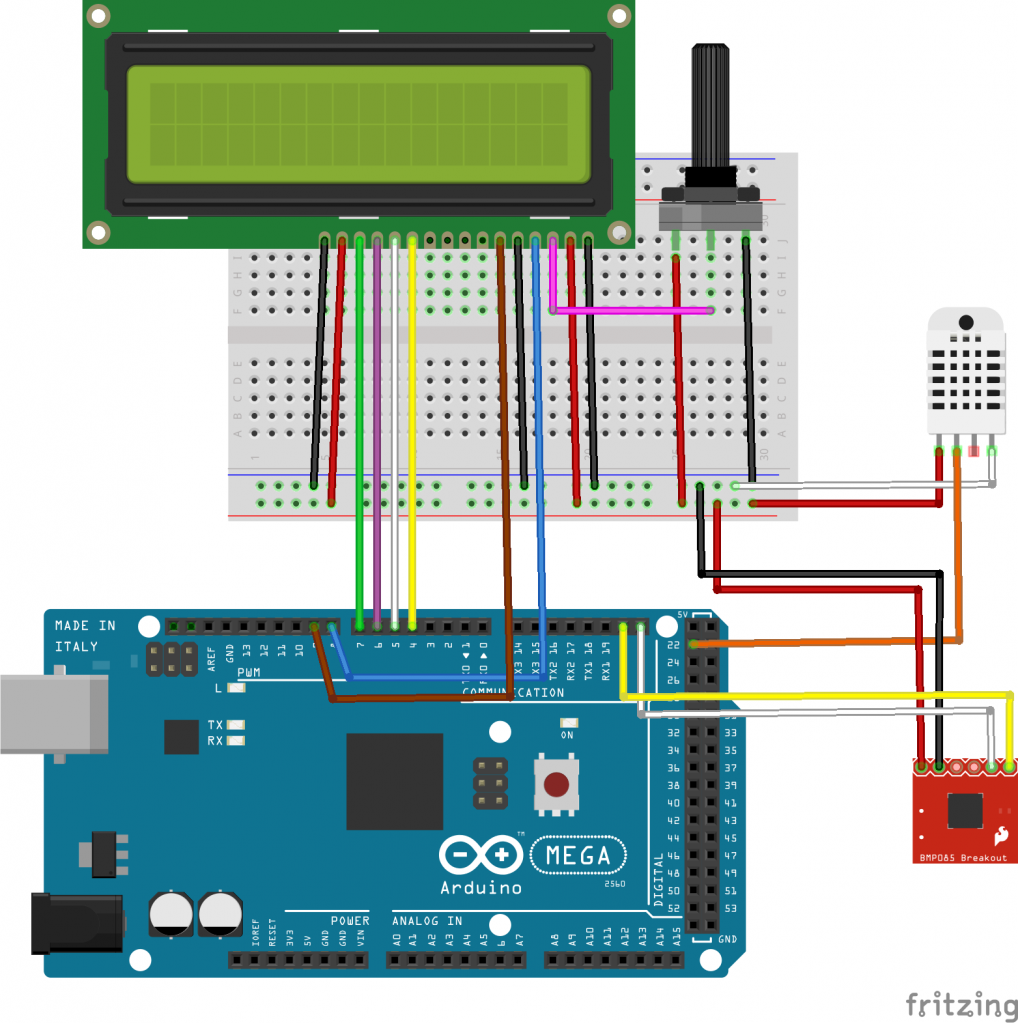
LCD Connection
LCD - Arduino
Pin 1(VSS) - GND
Pin 2(VDD) - 5V
Pin 3(VO) - Potentiometer middle pin
Pin 4(RS) - D8
Pin 5(RW) - GND
Pin 6(E) - D9
Pin 7-10 - GND OR FLOAT
Pin 11 - D4
Pin 12 - D5
Pin 13 - D6
Pin 14 - D7
Pin 15 - 5V
Pin 16 - GND
Note that the RW pin is connected to GND because we will be writing only to the LCD and not to read from it, for this to be possible the RW pin has to be pulled LOW.
If you are Using the LCD shield it will look like the image below after mounting.
BMP180 Connection
The pin connection of the BMP180 is as illustrated below. The SCL pin of the sensor will go to the SCL pin on the Arduino Mega which is on pin 21. Likewise the SDA pin will go to the SDA pin of the Mega on pin 20.
BMP180 - Arduino
VCC - 5V
GND - GND
SCL – D21 (SCL)
SDA – D20 (SDA)
DHT11 Connection
Pin connection of the DHT11 to the arduino is as illustrated below. All DHT11 sensors have three main functional pins. The DHT types with four pins always have a void pin which is never connected to anything.
DHT11 – Arduino
VCC - 5V
DATA - D22
GND - GND
With our connections all done, its time to write the code for this project.
Code
Before writing the code, we need to download two libraries. One for the BMP180 which can be downloaded from github. Click on download zip and when done extract it. Open the extracted file and then go to software, double-click on Arduino and then on libraries. Rename the folder “SFE_BMP180” to something simpler like “BMP180”, copy this folder and paste it in your Arduino libraries folder.
If you followed the previous tutorial then you don’t need to download DHT11 library. If you don’t have the library you can download it from github.
When done extract it into Arduino libraries folder, then open Arduino IDE.
The first thing to be done is to include all the dependencies the code needs to run fine, libraries in this case.
#include "DHT.h"
#include <LiquidCrystal.h>
#include <SFE_BMP180.h>
#include <Wire.h>
Next, we create an object called pressure and also create a global variable temperature of type float.
SFE_BMP180 pressure;

float temperature;
Next, we define altitude in other to get the correct measurement of the barometric pressure and we enter the value in meters. it is 216.0 meters in Sparta, Greece. I also defined the DHT pin and the type.
#define ALTITUDE 216.0 // Altitude in Sparta, Greece

#define DHTPIN 22     // what pin we're connected to

#define DHTTYPE DHT11

DHT dht(DHTPIN, DHTTYPE);
We create a DHT object and then pass in the pin number (DHTPIN) and the sensor type (DHTTYPE). The last line we create an LCD object, passing in the pin number our LCD pins are connected to as follows (lcd (RS, E, D4, D5, D6, D7)).
DHT dht(DHTPIN, DHTTYPE);
LiquidCrystal lcd(8,9,4,5,6,7);
In the setup function, we call the LCD begin method passing in the LCD size which is a 16×2. Next, we print on the first line of the LCD then call the DHT.begin() and the pressure.begin() methods.
void setup(void) {

  lcd.begin(16, 2);
  lcd.print("Reading sensors");
  dht.begin();
  pressure.begin();
}
In the loop function, the first line I created two variables “humidity” and “pressure” both of type int which will hold the humidity and pressure value.
float humidity, pressure;
The second line I added 10.0 to value got from the dht.readHumidity() method because I noticed my DHT11 sensor humidity value is off about 10 percent. In the third line, I called the function readPressureAndTemperatue() to read the pressure and temperature.
humidity = dht.readHumidity()+10.0f;
pressure = readPressureAndTemperature();
This function updates the global temperature variable and also returns the pressure value.
Next, in the loop function, I gave it a delay of two seconds after reading and then clear the LCD.
delay(2000);

lcd.clear();
Next we create three character arrays, two of size six and the last one of size 7. I used the dtostrf function to convert our temperature, humidity and pressure value from type float to string and then print it on the LCD. Note that the explicit typecasting used in the lcd.print() function ((char)223) is used to print the degree symbol on the display.
char tempF[6];
 char humF[6];
 char pressF[7];

 dtostrf(temperature, 5, 1, tempF);
 dtostrf(humidity, 2, 0, humF);
 dtostrf(pressure, 7, 2, pressF);

 //Printing Temperature
 lcd.print("T:");
 lcd.print(tempF);
 lcd.print((char)223);
 lcd.print("C ");
After getting the humidity, temperature and pressure we print it out on the LCD in a nicely formatted way.
//Printing Humidity
 lcd.print("H: ");
 lcd.print(humF);
 lcd.print("%");

 //Printing Pressure
 lcd.setCursor(0,1);
 lcd.print("P: ");
 lcd.print(pressF);
 lcd.print(" hPa");
Here is the complete code for this project.
#include "DHT.h"
#include <LiquidCrystal.h>
#include <SFE_BMP180.h>
#include <Wire.h>

SFE_BMP180 pressure;

float temperature;

#define ALTITUDE 216.0 // Altitude in Sparta, Greece

#define DHTPIN 22     // what pin we're connected to

#define DHTTYPE DHT11

DHT dht(DHTPIN, DHTTYPE);
LiquidCrystal lcd(8,9,4,5,6,7);

void setup(void) {

  lcd.begin(16, 2);
  lcd.print("Reading sensors");
  dht.begin();
  pressure.begin();
}

void loop() {

 float humidity, pressure;

 humidity = dht.readHumidity()+10.0f;
 pressure = readPressureAndTemperature();

 delay(2000);

 lcd.clear();

 char tempF[6];
 char humF[6];
 char pressF[7];

 dtostrf(temperature, 5, 1, tempF);
 dtostrf(humidity, 2, 0, humF);
 dtostrf(pressure, 7, 2, pressF);

 //Printing Temperature
 lcd.print("T:");
 lcd.print(tempF);
 lcd.print((char)223);
 lcd.print("C ");

 //Printing Humidity
 lcd.print("H: ");
 lcd.print(humF);
 lcd.print("%");

 //Printing Pressure
 lcd.setCursor(0,1);
 lcd.print("P: ");
 lcd.print(pressF);
 lcd.print(" hPa");
}

float readPressureAndTemperature()
{
  char status;
  double T,P,p0,a;

  status = pressure.startTemperature();
  if (status != 0)
  {
    delay(status);
    status = pressure.getTemperature(T);
    if (status != 0)
    {
      temperature = T;
      status = pressure.startPressure(3);
      if (status != 0)
      {
        delay(status);
        status = pressure.getPressure(P,T);
        if (status != 0)
        {
          p0 = pressure.sealevel(P,ALTITUDE);
          return p0;
        }
      }
    }
  }
}
Save your code, connect your Mega to your computer and make sure under your tools menu the board picked is “Arduino/Genuino Mega or Mega 2560” and also the right COM port is selected. Click upload when done.
Demo
After uploading the code to your Arduino, You should see something like the Image shown below.
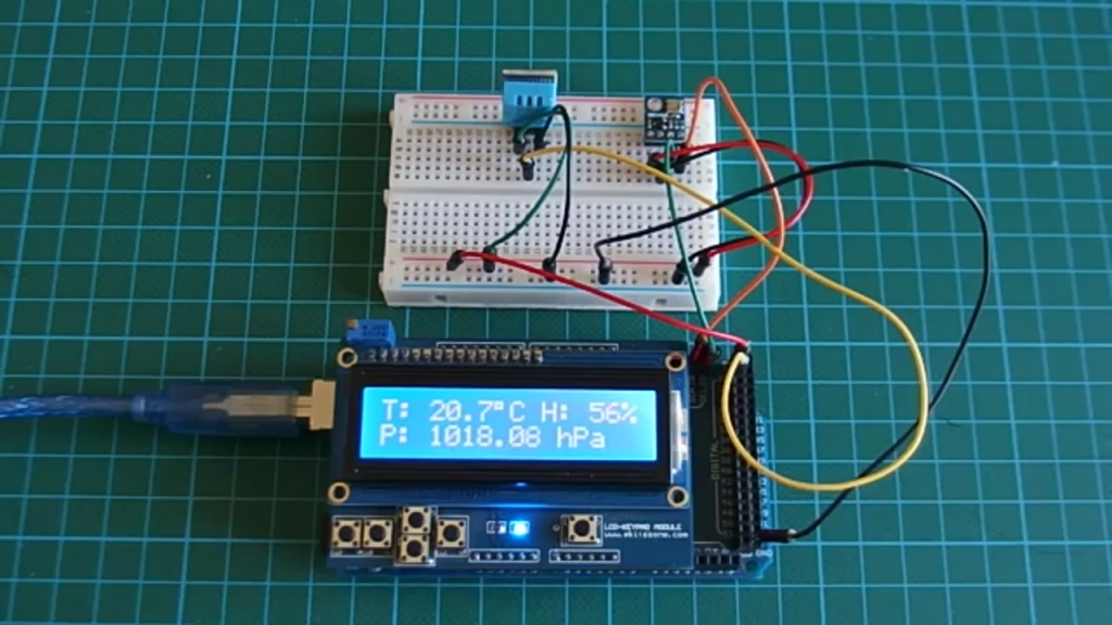
Worked right? Yea!!.
Visit here to download the code for this tutorial.
You can also watch a video tutorial on this topic on youtube.



Thank you for the project.
I have wired up the project as per your details and uploaded the code as provided.
Everything works well except for the humidity output. It basically does not output a value on the screed. It just states H= %. I have checked my wiring, changed the DHt11 with a new one and still get the same results.
I have used both the mega and uno and get the same results in each case
Any ideas on how I might rectify this.
There seems to be a connection issue between DHT11 and Arduino. Also check that the power is correct on DHT11 sensor.
Can I use this code in esp32 ?
It depends on the ESP32 board you have. If it is Arduino compatible then you can move on.
char tempF[8];
char humF[8];
char pressF[8];
This made my problem with humidity work
Can I use in this code in BMP280 sensor?
Same proble with the humidity any other ideas, i need to make this work for a shool project