Digitally Controlled 2.1 Channel Analog Audio Power Amplifier
- Dilshan R Jayakody
- jayakody2000lk@gmail.com
- 27.115 Views
- medium
- Non tested
This article introduces high quality digitally controlled 2.1 channel analog audio power amplifier system. This project is mainly based on TDA7377 AF power amplifier and PIC18F452 8bit microcontroller. Basic technical features of this receiver are covered in table1.
This unit is specifically design to work with PC sound cards, radio receivers and CD/DVD/Blue-Ray players.
Construction
This system use commonly available electronic components and substitute components can also use.
For maximum quality we recommended to use components from same manufacturer. For example some actual capacitor values and resistor values are slightly varied from manufacture to manufacturer, and this cause some minor unbalances in output of amplifiers. When soldering the PCB we suggested to soldering small components such as jumper wires, resistors first and moving to larger components at last.
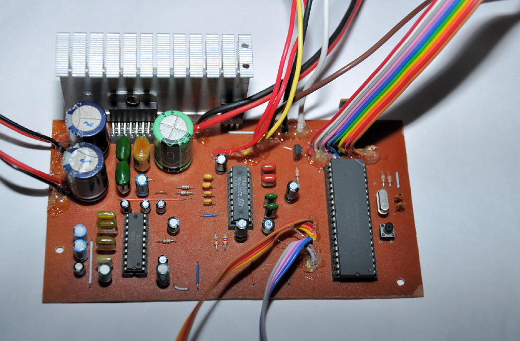
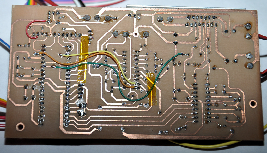
Also try to use IC sockets for all the DIP and TDA7377 ICs. In our prototype all the integrated circuits except 2 voltage regulators (IC5 – 7805 and IC6 – 7808) are connected to mainboard via IC sockets. All the controls, I/O and power terminals and display modules are connected to mainboard through wires, and for control and display lines we recommended to use suitable ribbon cables. For power and output wires 18-20 gauge multi-strand cables are recommended (these wires are commonly used for automotive wirings). In given PCB design 4 wires need to be installed for I2C bus and MCU STAND-BY lines. For this, standard Teflon coated 32-30 gauge wires are sufficient.
Microcontroller firmware and source code
This project is an open hardware project and all the source codes of PIC18F452 MCU are available to download at project website. The source code of PIC18F452 is written using MikroC for PIC compiler and free version of this compiler is available to download at Mikroelektronika[1] home page. Currently available firmware is design for 8MHz clock and other required MCU related settings are listed in table 2. Compiled HEX file for PIC18F452 is also available to download at project website.
[1]: Mikroelectronika home page is http://www.mikroe.com. MikroC for PIC is available to download at http://www.mikroe.com/mikroc/pic
Testing the system
After assembling the system it is necessary to check all the power connections are working properly in this system. To check power lines follow the steps in below:
- Connect both AGND and DGND together and from here onwards this connection is referred as GND.
- Unplug TDA7377, TDA7315, LA2650, PIC18F452 and 1602 LCD module from the mainboard.
- Disconnect any audio inputs and outputs.
- Supply 12V 14V DC input to GND and V+ lines.
- Check the voltages between IC pins which are listed in table3.
If voltage readings are correct, plug all the ICs and LCD module and hold down the SYSTEM-RESET button and apply power to the system. While holding the SYSTEM-RESET button press.
POWER ON/OFF button and turn on the system. Once you got the LCD on, release the SYSTEM-RESET button and adjust the controls and check the audio outputs. After firmware update or at initial run, pressing the SYSTEM-RESET button is essential to avoid any damages to speakers due to high volume levels.
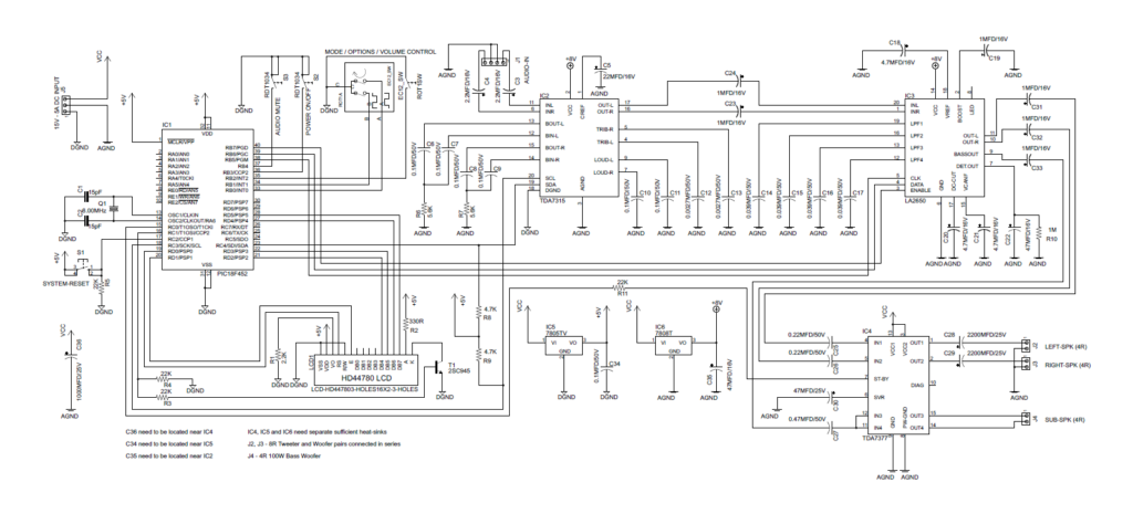
Schematic
Firmware
Parts List
Troubleshooting
The most common problem can occur in this amplifier system is no audio from the power amplifier IC. The most possible reasons are excess supply voltage (which is above 18V) or short circuits in output terminals of amplifier. TDA7377 is equipped with several protection features and state of the protection system can be monitored through Pin 10 of TDA7377 IC.
Second most common issue is LCD with 16×2 boxes. This occurs due to initialization problems of HD44780 controller. A common reason for this issue is wrong wiring or faulty PORTD outputs.
If LCD output is too light (or dimmed), change the value of R1 (2.2KΩ) resistor. We set this value for commonly available Blue/White 1602 LCD module.






Sir the program not working. 27 and 28 pin are high. It will not change
Have you build the schematic? Check that you flashed the mcu correctly and that fuses are right.
I tried in protious software
Yes i buld with the compailer of micro c pro for PIC
After build an error occur “main function not defined” message No357