

Motorcycle Universal Gear Indicator
- Vassilis Papanikolaou
- vpapanik@gmail.com
- 205.139 Views
- medium
- Tested
- 4 Likes

Introduction
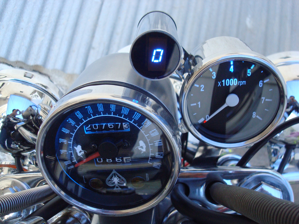
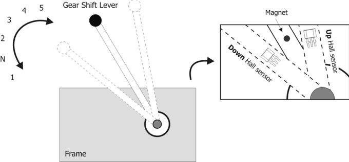
This is a new design for a universal gear indicator that can be fitted to any motorcycle as an aftermarket accessory. Its main advantage is that its operation depends entirely on the gear shift lever movement, instead of connecting to speedometer and tachometer sensors (found in expensive commercial devices), which are rarely available in older motorcycles. It consists of a main circuit including a 7‑segment LED indicator, two Hall sensors that are attached to the motorcycle frame, and a small magnet placed on the gear shift lever.
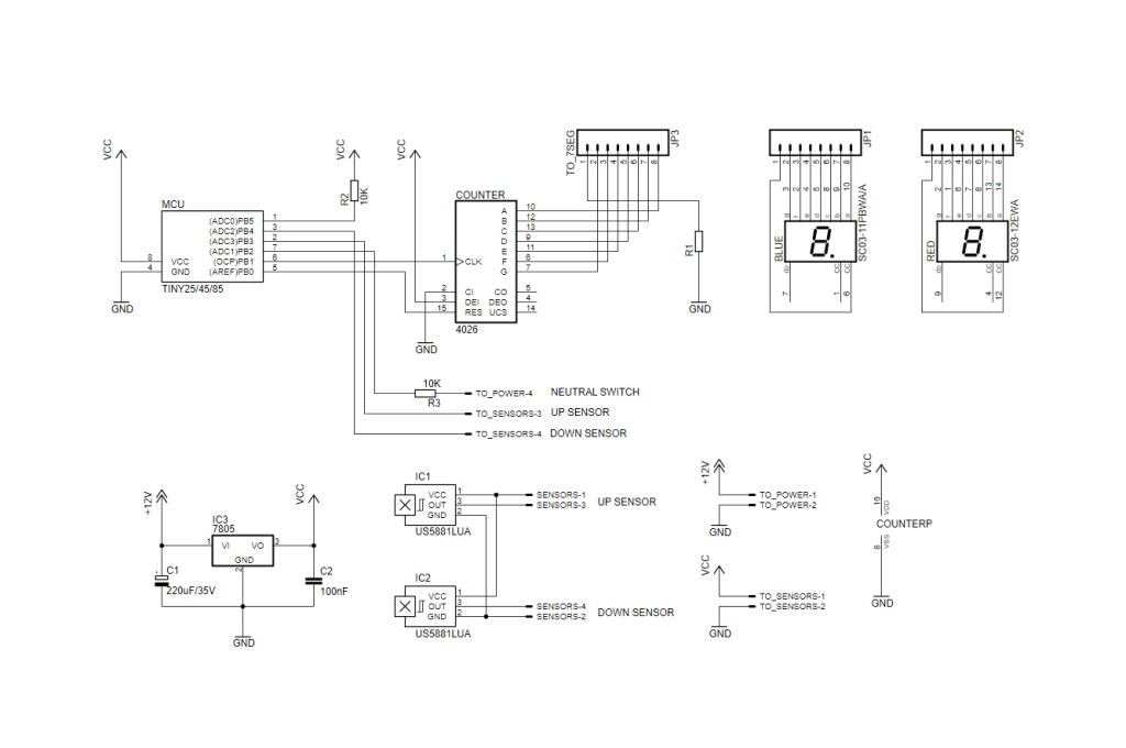
The main circuit is based on an AVR ATTINY25/45/85 microcontroller, which reads the signals of the two Hall sensors and the neutral switch and outputs the current gear number to a 7‑segment LED indicator, through a 4026 counter/decoder.
At maximum output power there is significant heat produced by IC1 and for that reason we mounted it directly on the ground plane to achieve maximum heat radiation.
Schematic
Source Code
The source code is written in AVR-GCC (WinAVR) and can be programmed with the default fuses using an AVR programmer (default : ATTINY25 microcontroller and USBTiny programmer). Moreover, the constant TOP_GEAR 5 should be changed to 6 for six-gear motorbikes. Source code can be downloaded on the download section below.
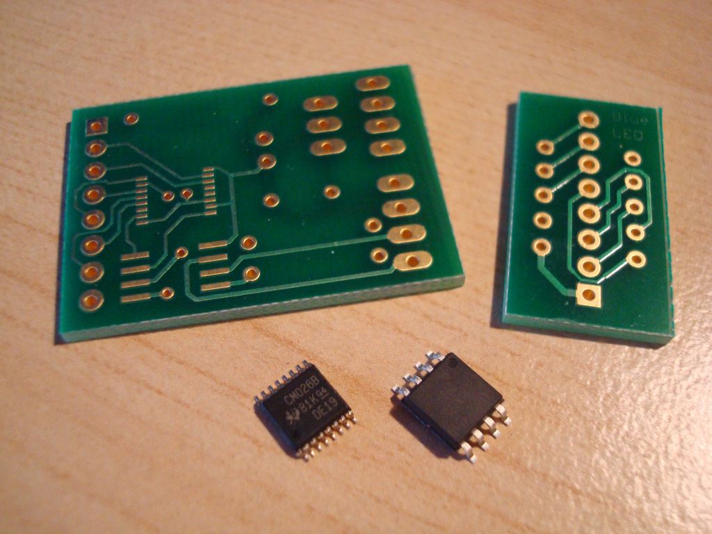
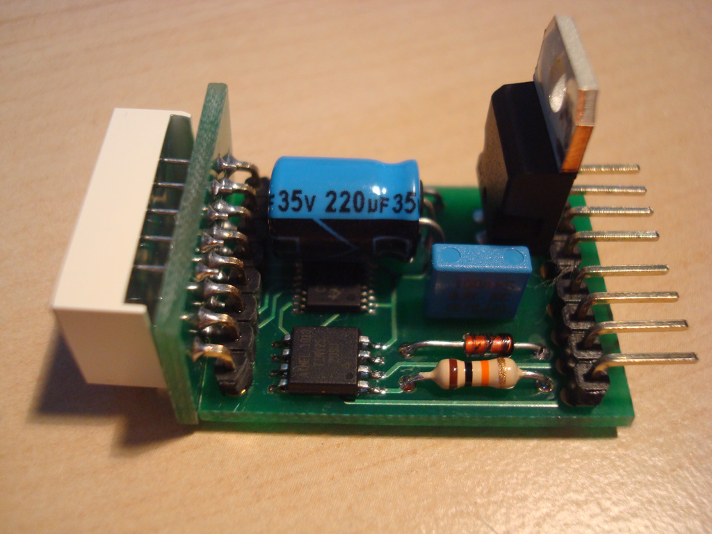
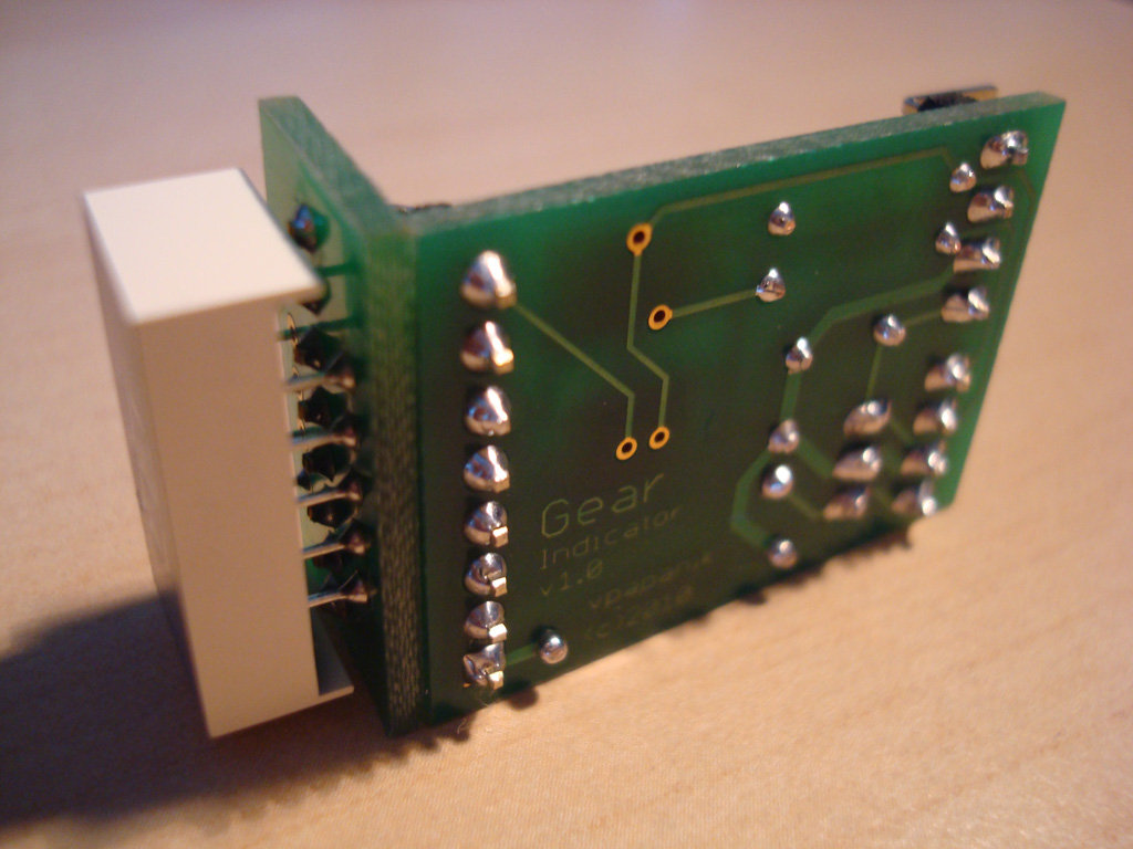
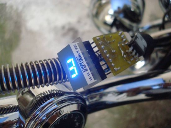
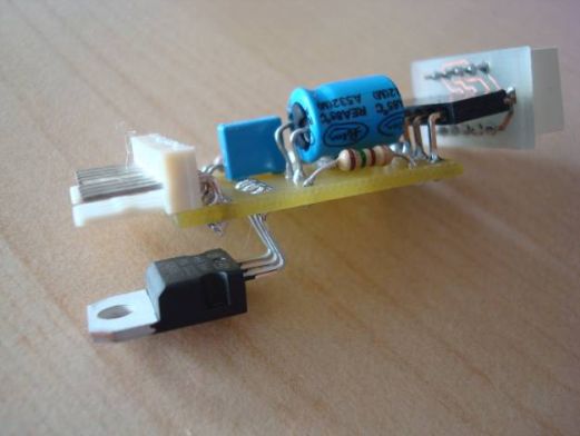
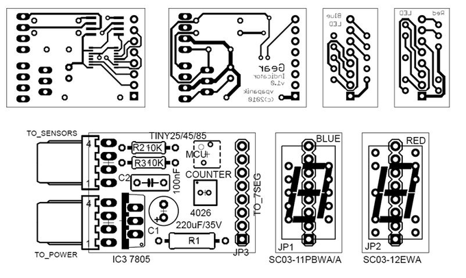
PCB Design
The suggested implementation for the main circuit is a small size, double-sided PCB, with SMD packages for the microcontroller and the decoder ICs. The 7-segment LED is placed in a secondary PCB, connected vertically to the main one in a modular fashion (see pictures). Two PCBs for different Kingbright LED footprints (red and blue) are also provided.

Parts List
| R1 | 10 to 220 Ω ½W | Depending on preferred LED brightness |
| R2, R3 | 10 ΚΩ ¼W | – |
| C1 | 220 μF / 35V | Electrolytic capacitor |
| C2 | 100 nF | MKT/polyester capacitor |
| MCU | ATTINY25/45/85 | Mouser Part 556-ATTINY25-20SU |
| COUNTER | 4026 | Mouser Part 595-CD4026BPWE4 |
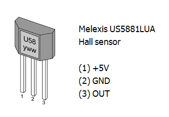
| IC1, IC2 | Hall sensor | Melexis US5881LUA |
| IC3 | 7805 | 5V Regulator TO-220 |
| BLUE | Kingbright 0.3″ | Mouser part 604-SC03-11PBWA/A |
| RED | Kingbright 0.3″ | Mouser part 604-SC03-12EWA |
| JPx | Pin connectors | As shown in silkscreen and pictures |
Possible improvement
In the current design, when the neutral switch is open (there is a gear on), there appears to be a very small current (< 0.5 mA) sinking through R3, due to the voltage difference between the neutral switch connection (TO_POWER-4) and the microcontroller. If the neutral indicator is of LED type (not a resistor bulb), there is a possibility that it stays dimmed, instead of being completely off. In that case, a small switching diode (1N4148) can nicely replace R3 (on the same PCB) in order to block this small incoming current when the neutral switch is open, as shown in the figure below :

For a better insight in the above issue, the following script can be imported in Paul Falstad’s excellent circuit simulator:
http://www.falstad.com/circuit
$ 1 5.0E-6 10.20027730826997 62 5.0 50
R 192 96 192 48 0 0 40.0 5.0 0.0 0.0 0.5
R 512 96 512 48 0 0 40.0 12.0 0.0 0.0 0.5
r 192 96 192 176 0 10000.0
x 231 142 309 145 0 12 internal pullup
x 125 25 277 31 0 24 Gear Indicator
x 456 26 571 32 0 24 Motorcycle
M 192 176 96 176 0 2.0
x 65 157 118 160 0 12 AVR Input
w 192 176 192 256 0
162 512 96 512 160 1 2.1024259 1.0 0.0 0.0
r 512 160 512 256 0 470.0
d 512 320 512 400 1 0.805904783
x 413 388 499 391 0 12 protective diode
s 512 400 640 400 0 1 false
g 640 400 640 448 0
x 539 422 615 425 0 12 neutral switch
x 309 240 391 246 0 24 1N4148
x 132 377 269 380 0 12 in place of R3, and watch
d 304 256 400 256 1 0.805904783
r 304 336 400 336 0 10000.0
x 337 371 367 377 0 24 R3
S 192 320 272 320 0 1 false 0
w 192 256 192 320 0
w 304 256 272 256 0
w 272 256 272 304 0
w 304 336 272 336 0
w 400 256 400 304 0
w 400 304 448 304 0
w 400 336 400 304 0
w 448 304 512 304 0
w 512 304 512 320 0
w 512 304 512 256 0
x 131 359 276 362 0 12 flip switch to insert a diode
x 134 394 272 397 0 12 current drop to zero when
x 134 412 254 415 0 12 neutral switch is open
… or click here for direct Circuit Simulator Link
Contributed by Brett Walach
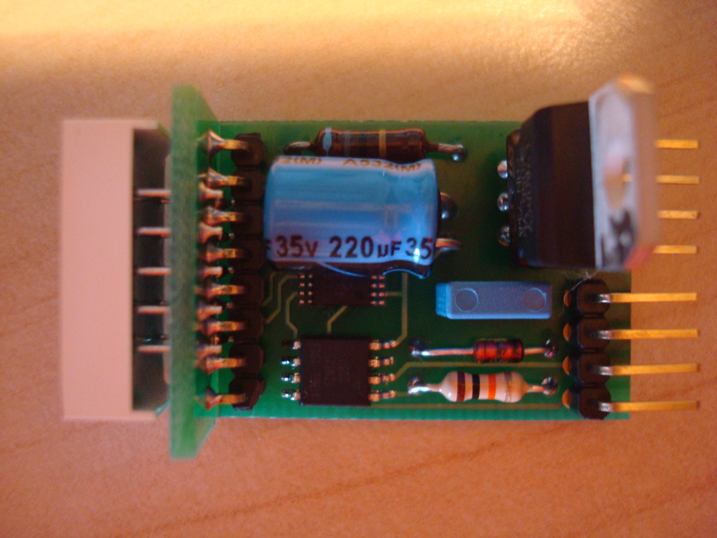
Photos
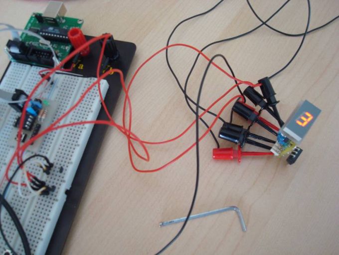
Connections
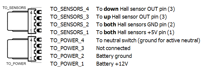
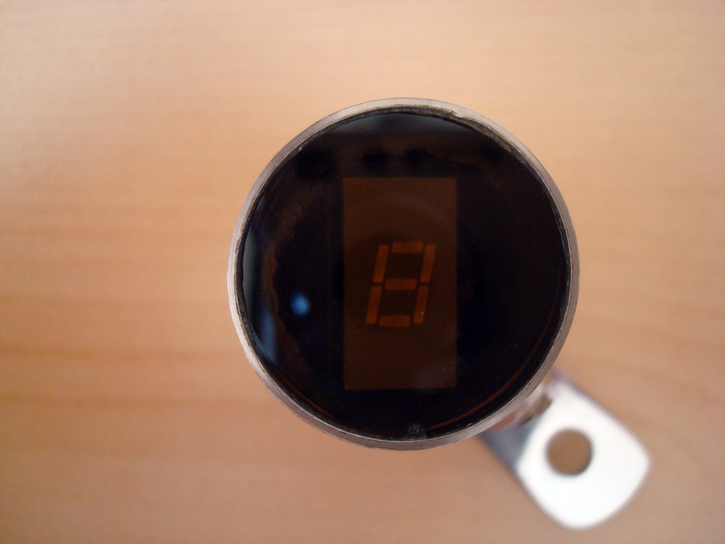
A successful circuit build will do a self-test when connected solely to 12V power (pins TO_POWER_1 and TO_POWER_2), by cycling through all digits on the 7-segment display (see video below). After the self-test, the current gear will be shown and can be changed by the shift lever movement. Note that a gear is changed when the magnet’s south pole is drawn away from the sensor (north pole will not work). Moreover, if a neutral gear is detected (from the neutral switch connected to TO_POWER_4), the display resets to zero (also acting as a self-calibrating feature if anything goes wrong). Finally, when the power is turned off, the last shown gear is stored in the MCU’s flash EEPROM and restored when the device is turned on again.
The following video shows the initialization procedure of the gear indicator :
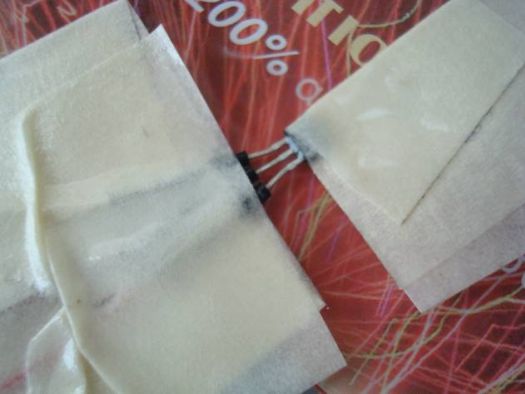
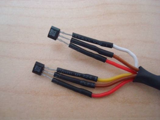
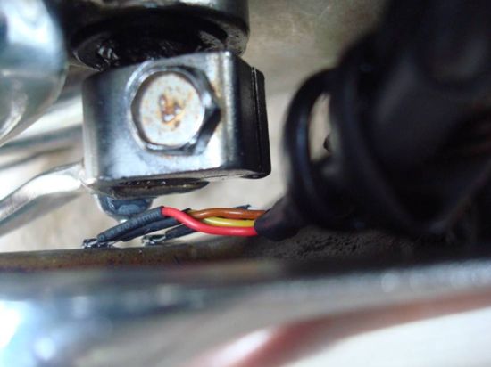
Sensor Cable
The following photos show the construction of the 4-wire sensors cable that is plugged to the TO_SENSORS connector. The visible sensor pin parts should be covered with plastic lacquer for protection as well.
After putting it all together the circuit is now operative and ready to be installed on the motorcycle. A video showing a simulation of gear shifting (by hand) is available below :
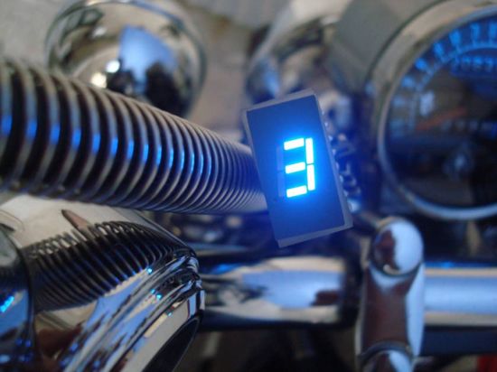
Installation Photos
Here are some photos and videos from the installation on my Suzuki Intruder VS400


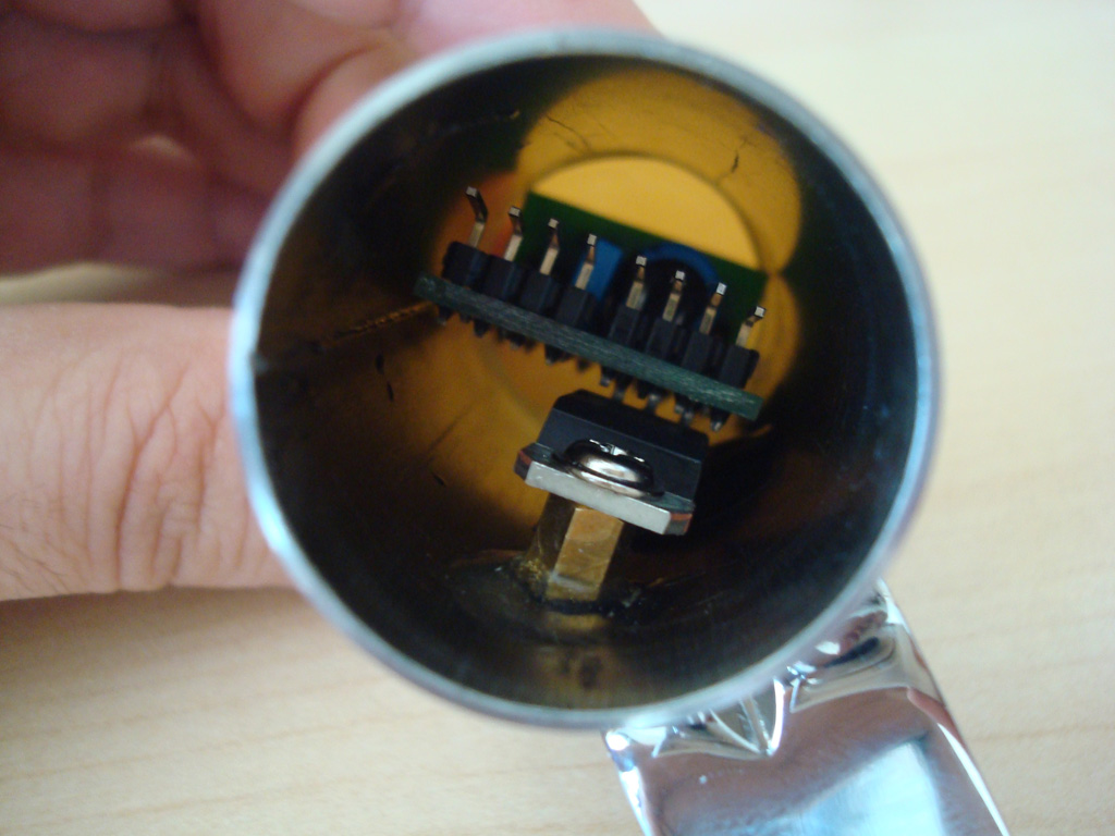
Custom Housing
Installation Videos
Installation1 – Gear shifting by hand
Installation2 – Real gear shifting with engine on
Installation3 – Storing last gear in EEPROM
Thanks for reading !
Designed and built by Vassilis Papanikolaou © 2010
Please follow and like us:
PCB


 – Variable Reluctance Magnetic Pickup to Voltage Converter")


Any source code for cub type motorcycle ?
What is the cost of the Universal Gear Indicator ?
Sorry, it’s not for sale.
Which vehicle do you need this for?
It’s universal and it will fit almost all bikes, as long as you place the sensors in correct place.
please tell me. put together your project, but I have no response to UP and Netral inputs. And the switching goes from 0 to 9. Tell me where I did something wrong
The cylinder case / housing seems impressive, how did you make it?
Isn’t there a video making this?
Good day, Mr. Papanikolaou! I am about to make that gear indicator for me but faced a problem with programming the MCU. Could you comment more on this…any clue please! I have AVR USBasp programmer on hand and tried AVRdude and Khazama soft. Both apps communicate with the board but the result is always like “…target doesn’t respond” and “…wrong id…” The mcu is Attiny25.
Thanks for sharing this project @Michail Papadimitriou ! I will try to make a couple myself! any feedback or warnings I should note after so many years you created this? thanks!
@Vassilis Papanikolaou originally designed this project, and i would suggest you go on building and post any queries that arise here in the community. Thanks