
PIC16F84A discolight effect with bass beat control
- Zsolt Bitter
- tracid1987@yahoo.com
- 18.990 Views
- advanced
- Non tested
- 0 Likes

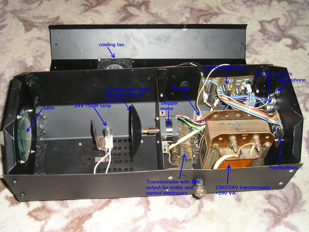
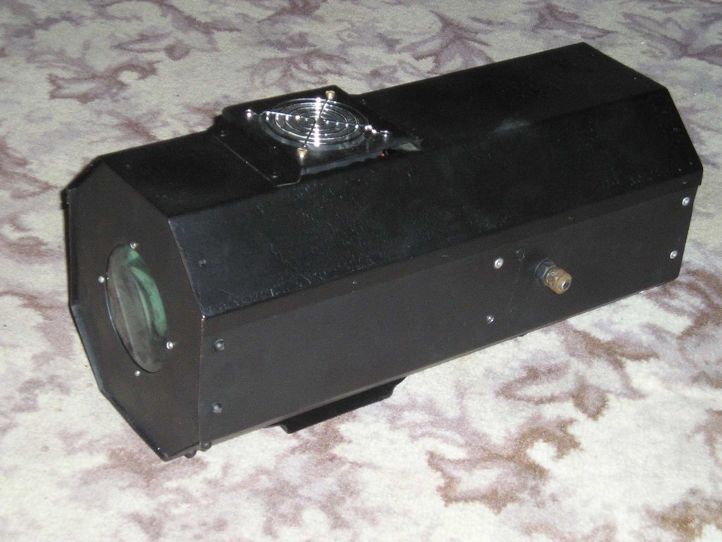
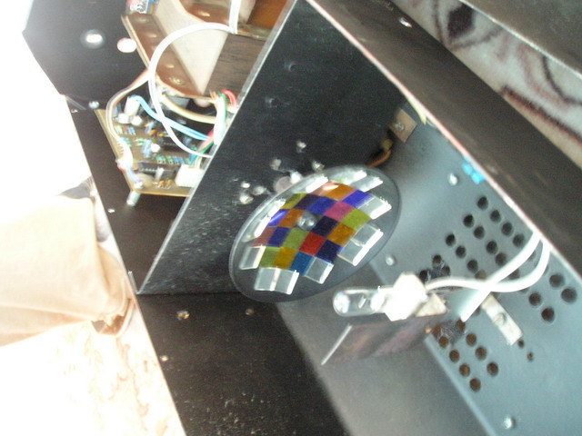
This is an early picture of my discolight effect. Because of the AGC circuit theres no need for potentionmeters for sensitivity adjust. I replaced them with trimmers. Now the microphone is on the control electronics because theres no need to place it outside the box and the possible noises from the surroundings are reduced.
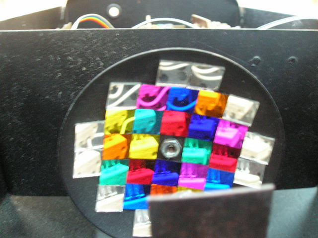
You have to choose the distance between Lens-Lamp-Parabola to get sharp beams. Its all about optics.That little ΄wall΄(hindrance) before the Lamp doesnt let the white light to pass through the Lens.
I have that box from a friend who had there a bigger home-made parabola. So the box with mine could be smaller but i didnt want to resize it.Its OK.
Introduction
External circuit converts bass beat of music into pulses.The motor is controlled by them.
If theres bass beat recognised then the motor rotates one direction(in full stepping) for a predefined time then stops. If the second beat comes in then it rotates again for the same time and so on.There is a random number generator (from 1 to 4) written into the code which tells how many times have the motor to rotate one direction.After that the PIC changes rotation direction of the motor.If the tempo is too fast (<400msec) then the direction is changed immediately.
When the motor stops after the predefined time period a counter is enabled.if beat doesnt come in for 15sec the motor starts to rotate slowly in half stepping.If a beat comes in the counter is disabled and the motor continues its normal rotation in full stepping.
(Half stepping is smoother but unfortunately the torque is less)
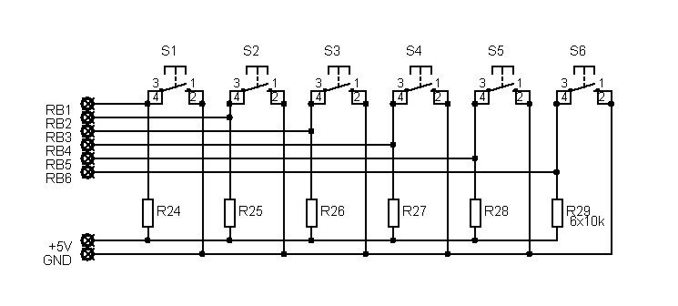
The PIC can control the motor after every beat or its possible to bypass some beats.It can be done by pushbuttons. Rotation speed and rotation lenght can be adjusted too.Settings are limited between values to prevent possible register overflow-underflow. These values are saved in EEPROM so after shut-down the settings dont lost.
A beat consist of a series of vibrations(dont know the correct english word for that-sorry) so the PIC gets a few
interrupts.To prevent multi-triggering theres a counter written into the code which disables reaction to beat for
200msecs after the first interrupt. 180msec delay is enough if you are using amplifiers output (or line out) as music source. I had to increase it to 200msec because i use microphone and the rooms echo influences operation.
Programming the PIC – Adjustments
When programming the PIC16F84A you need to fill the first three EEPROM locations with the setting values.
I used these one: 01 14 E0
I programmed the PIC with Ic-Prog using a simple JDM programmer.
After you succesfully built the whole hardware you need to adjust the trimmers very precisely. If you dont experiment a few times with adjusting them then its possible that the PIC will not recognise every beat because of the small amplifycation level. Or,it will do several things at only one beat.So you have to find the best adjustment.
The original circuit which converts bass beat into pulses is from Dan Frasers ΄Audio trigger circuit for light chasers΄
(updated by Tomi Engdahl). I only replaced the line-out control with microphone and removed the 555 circuitry
because of the software solution. The very-own in this project is the software for the PIC microcontroller.
Block diagram and software flowchart
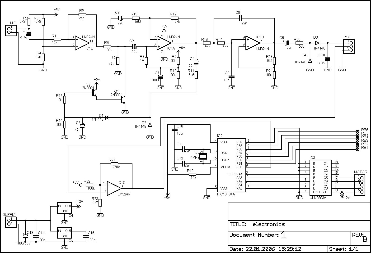
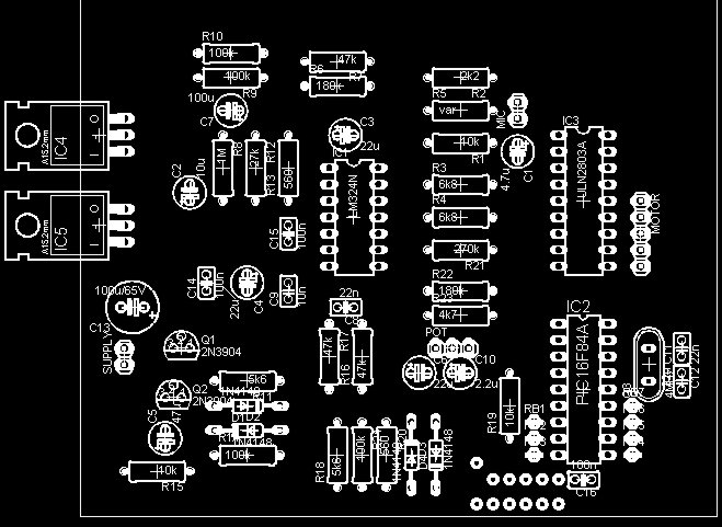
Schematics
Conclusion

This is my first PIC project.While I developed the code i learnt very much about coding a PIC. If you are interested in building it up please let me know!I would really like to know if my project is useful for other people too.
Please follow and like us:
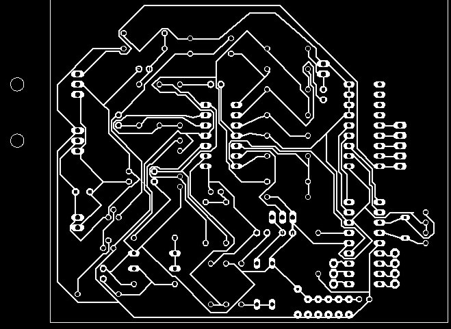
PCB


Subscribe
Login
0 Comments