Halloween Scare using 12F683 and ISD2532
- Rui Cabral
- http://www.ruijc.webnode.com
- rui.j.cabral@googlemail.com
- 12.817 Views
- medium
- Non tested
- 0 Likes

Introduction
Halloween is coming up and it’s time to do some pranks.
Everyone likes Halloween and I’m no exception. Every year me and my wife decorate the house with lot’s of bugs, spider webs, creepy posters and of course lot’s of Halloween candy.
While making the normal Halloween preparations I came up with the idea of making a circuit that would make some scary noises and also would react to movement.
I expect to get some screams and laughs from friends that come to visit us this year.
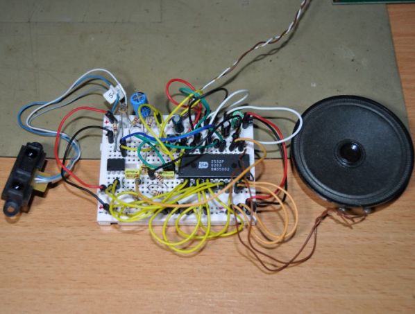
The circuit is basically a sound chip that records and stores sounds in memory and plays them back with a microcontroller and it’s triggered by light and motion.
The sound chip is from maker winbond and has a very good sound quality.
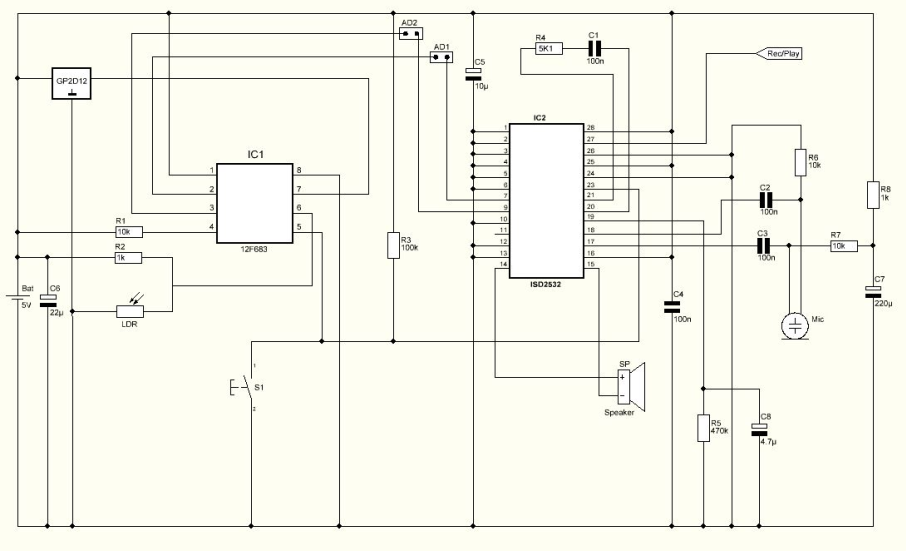
Schematic
Parts List
R1 10K ohms resistor
R2 1K ohms resistor
R3 100K ohms resistor
R4 5K1 ohms resistor
R5 470K ohms resistor
R6 10K ohms resistor
R7 10K ohms resistor
R8 1K ohms resistor
LDR Light dependent resistor
C1 100nF capacitor
C2 100nF capacitor
C3 100nF capacitor
C4 100nF capacitor
C5 10uF capacitor
C6 22uF capacitor
C7 220uF capacitor
C8 4.7uF capacitor
SENSOR GP2D12 from Sharp
IC1 12F683 microcontroller from Microchip
IC2 ISD 2532 from winbond
S1 Push button
SP Speaker
MIC Electret microphone
Others:
Box
PCB
Jumpers
4.8V Battery Pack
Hex program for the microcontroller
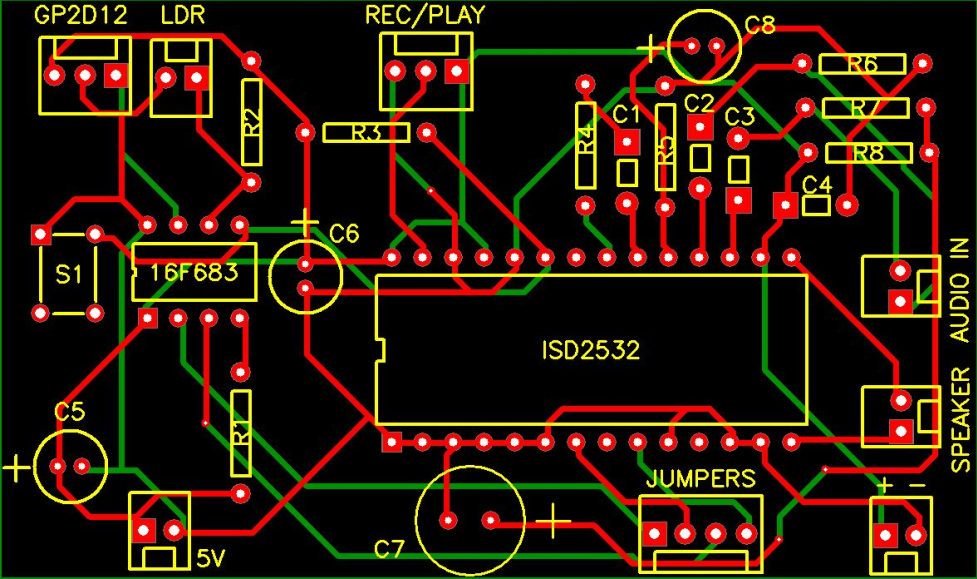
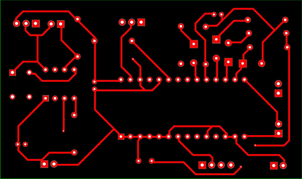
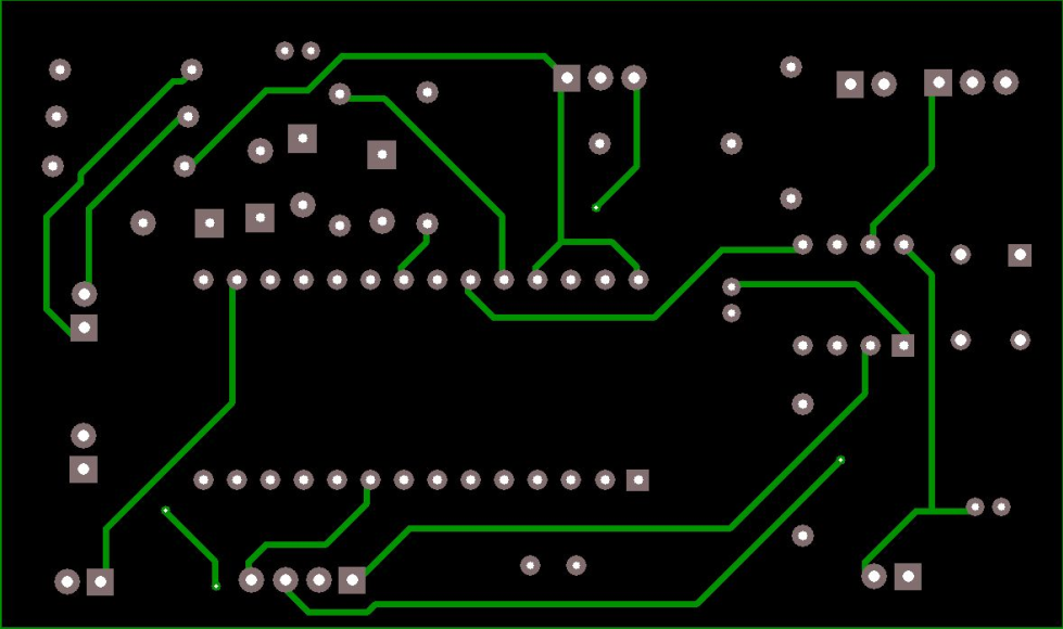
PCB
The PCB, which you can find it below, used for this Project is double layer and its size is 80.66 mm x 47.70 mm.
How it works
This circuit has 2 sensors. One motion sensor ( Sharp GP2D12 ) and a light sensor ( LDR ). The microcontroller monitors both sensors and triggers the sound chip in certain conditions.
Every time the circuit is powered on, the microcontroller stores the distance read by the sharp sensor and uses this as reference for the space available for object/people detection. Anything moving in front of the sensor up to that reference activates the first stored sound.
The other 3 sounds are time triggered only when the light is out. The LDR senses the light intensity and only when placed in darkness it will activate the remaining sounds. Sometimes the sounds are individually played and sometimes combined. There are 4 sounds slots available with max. length of 6 seconds each.
How to record sounds
The PCB has some connectors with jumpers making it possible to change from record to playback mode and vice versa.
Connector #1 named REC/PLAY is a 3 pin connector and jumper connection must be placed to the left side for record mode or to the right side for playback mode.
Also connector #2 named Jumpers must have 2 jumpers installed for playback mode. This is responsible for the memory address of the sounds.
When in record mode, some wire jumper connections must be made to change the address of the recordings manually connecting pin 2 and 3 to VDD or VSS according to table bellow:
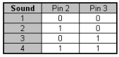
For VDD and VSS connections it’s possible to use connector named + –
Recording: With power off, connect a microphone, move jumper to record mode and connect message pin 2 and pin 3 to VSS.
- Turn on the power and prepare the sound you wish to record for #1 sound.
- Press and keep the S1 push button while recording. Release the button to stop recording.
- Connect pin 2 to VDD and keep pin 3 to VSS – this will address sound #2.
- Press and keep the S1 push button while recording. Release the button to stop recording.
- Connect pin 2 to VSS and pin 3 to VDD – this will address sound #3.
- Press and keep the S1 push button while recording. Release the button to stop recording.
- Connect pin 2 to VDD and keep pin 3 to VDD – this will address sound #4.
- Press and keep the S1 push button while recording. Release the button to stop recording.
- Turn the power off, disconnect microphone, restore address jumpers and move jumper to playback mode.
Hex Program
The Hex program named HSCARE.HEX, which can be found below must be saved in the 12F683 microcontroller’s memory before soldering on the PCB.
Assembly and testing
After soldering all components on the PCB and once all sounds are recorded it’s time to get it inside a box. I’ve found the perfect box for this project… this skull.

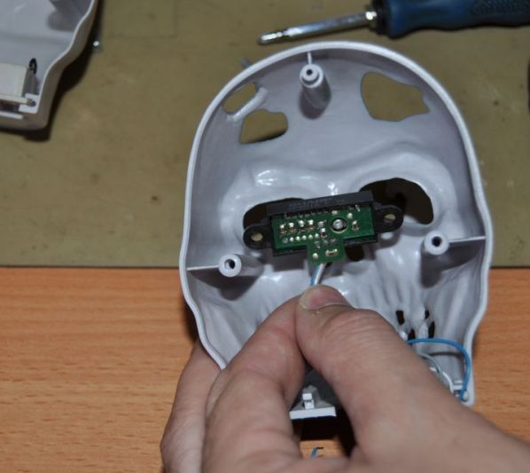
Placing the motion sensor in the eye section.

The sharp sensor adds a crazy eyes look to this skull.

The skull is ready to make some noise and scare the visitors.
Conclusion
This is a very cool Halloween project. It’s possible to record personalized sounds making this even more interesting. I bet that this project will bring many screams and laughs.
Please follow and like us:
PCB


Subscribe
Login
0 Comments