

Digital Volt and Amp Meter with Temperature Control
- RSABear (C) 2008
- 30.820 Views
- medium
- Non tested
- 0 Likes

Introduction
This project was designed and constructed as enhancement to the 0-30V Stabilized Power Supply Project with the DIY electronics hobbyist in mind. The circuit uses a single PIC Microchip to perform the Voltage, Current and Temperature conversions and display functions. The PCB Board uses large tracks and can easily be made using the “press-n-peel” method and a hobby drill. Components should be readily available anywhere in the world. Furthermore the hex files are available for the PIC16F877A and the PIC16F887 and the display can either be LCD or LED.
Warnings
There is only one warning – do not attempt to construct this project unless you are sure what you are doing. Nobody else but you can make the decision to construct it and therefore you are solely responsible for what you are doing or not doing with it.
Programming
The PIC Microchip Processor must be programmed before it will function as a Volt & Amp meter. There are many internet sites and PIC programmers that you can use. I used a Microchip MPLAB ICD 2 during the project. You might need to made changes to the circuit to accommodate a different type of programmer, do read the programmers instructions carefully.
Specifications
The circuit relies on the internal analogue to digital converter (ADC) of the PIC Microchip Processor. The accuracy is dependant on scaling the input voltage for the ADC for all three measurements. The good news is that both the PIC’s which can be used for this project have 10-Bit resolution ADC units which should work adequately in most circumstances.
In order to determine the resolution, simple to advanced mathematics can be used – I will use simple mathematics and present a basic explanation in order for you to get going on the project.
The Voltage of the PSU can be adjusted from 0 to 33V depending on the components in your circuit. The PIC can only measure voltages between 0 – 5V and represent the values measured as a 10bit binary number from 0 – 1024. In order to determine the voltage increments which can be measured one has to divide the scaled input voltage by 1024 and that equals: 33V/1024 = 32.2mV.
Similarly the current range is 0 to 3A. Which means that we can measure in 3.0/1024 = 2.9mA increments in a near perfect circuit.
Best Voltage resolution at 33.0V – 32.2mV
Best Current resolution at 3.0A – 2.9mA
Features
Either a LED or LCD display can be used:
- LCD Output is compatible with most LCD Displays with a HD44780 drive chip, it was designed for a 2 line x 16 character display
- 6 x 7 Segment LED Display using Common Anode displays
- Configuration via RS232 terminal to set Voltage and Current conversion factors
- Two PIC16F processors are supported, the 16F877A and 16F887 – separate hex files provided for download here
- IPSC Connector for Programming the PIC in circuit
- Separate -12V – 0 – +12V, Power Supply
Schematic Diagrams
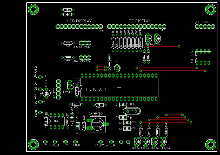
Processor
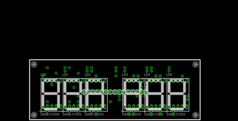
LED Display
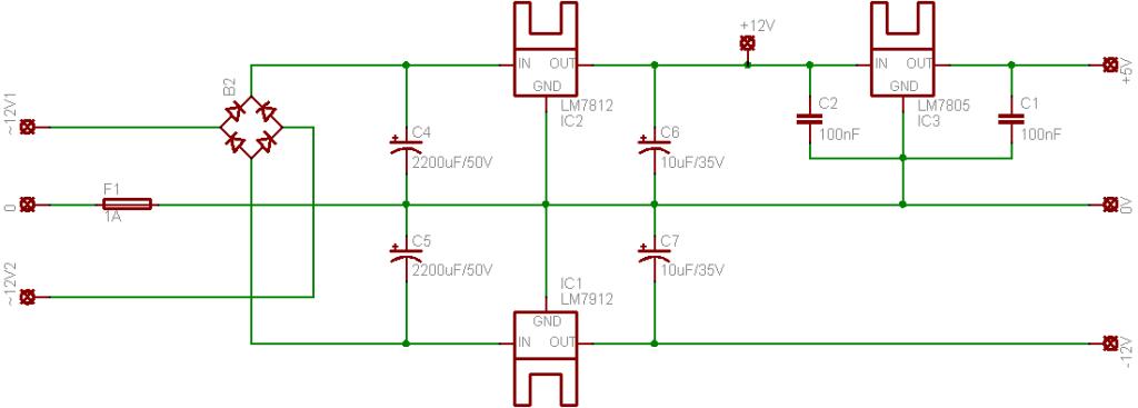
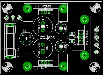
PSU Schematic
The power supply requires a small 12-0-12 transformer not shown on the schematic. The circuit draws around 100mA. I used a 10VA transformer – please adjust the value of the fuse to project your transformer. The heatsinks had a SK145-25 part number on the packet, I am not sure if it is easily available.
Theory
Voltage
R17 and VR1 form a voltage divider as input to the ADC Input of the PIC. As the input voltage changes, so will the output of the Voltage divider on PIN 3 of the PIC. When calibrating the project for use it is important to remove the PIC from the circuit and adjust the Value of VR1 in such a manner that the output of the Voltage divider is never greater than 5.0V. Failing to do so might damage the PIC.
Current
The current measurement is more complex and involves an Op-Amp configured as an inverting amplifier to provide the input for the PIC. The resistor R7, in the Power Supply circuit is used as a shunt resistor. The small voltage drop across the resistor varies according to the amount of current a given load will draw from the PSU. In order to measure with greater accuracy the small voltage drop is amplified using an Op-Amp circuit.
Using the formula for an inverting amplifier the output voltage of the Op-Amp can be calculated as follows:
1. The maximum current through R7 maybe 3.0A
2. The voltage drop over R7 = V = I * R = 3.0A * 0.47R = 1.41V
3. Op-Amp output = Vout = -(R12/R16)(Vin) = -(33K/10K)/1.41V = -4.653V. However, the input is a negative voltage and if we negate the answer we should measure close to 4.653V for the maximum load.
Fan Control
For cooling the main heatsink a third channel on the PIC’s ADC is used to measure the temperature and control a small fan. For this purpose a NTC Thermistor with a value of 10K is used. The NTC Thermistor is a device which reduces in resistance as the temperature increases. The same principal of a voltage divider is used to produce a voltage output which will allow the PIC to be used to determine the temperature measurement. The NTC Thermistor is connected in series with a 10K resistor R19 to produce a variable voltage output the PIC will compare to a setpoint to determine if the fan will be switched on.
Electrical Setup
It is highly recommended to use IC sockets on the PCB. This will greatly assist with setting up the project.
Voltage:
Remove all the ICs from the PCB
Adjust the PSU for the lowest output 0V
Adjust VR1 to its middle or halfway position
Connect the Voltage inputs CH1_0V and CH1_IN to the output of the PSU.
Connect a DVM to the 0V and PIN 3 of the 40 PIN IC socket
Adjust the output of the PSU and follow the increase and decrease of voltage on the output of the voltage divider
Adjust the PSU to deliver this maximum output
Now adjust VR1 to until the DVM measures 5.00V at the maximum output of the PSU
Current:
Remove all the ICs from the PCB
Connect a dummy load to the PSU, for calibration I used a 12V globe drawing 690mA
Now connect the DVM to the CH0_0 and CH0_IN connections
Add and remove the dummy load and note down the increase and decrease in the voltage drop over R7 and the inputs of the Op-Amp. CH0_IN should measure negative in respect to CH0_0.
Now insert the OP-Amp into the IC socket and apply the power to the processor board from the -12 – 0 – +12V PSU
The output of the Op-Amp PIN 6, must have a positive voltage with the dummy load connected and should be close to the value calculated as follows:
- As an example, I will use the 690mA 12V globe.
- Voltage over R7 = (0.69*0.47) = 0.3243V
- PIN 6 V (out) = (33K / 10K) * 0.3243V = 1.070V
- The exact Voltage is not important, as long as it is close to 1.070V and drops to 0V when the dummy load is removed.
Ensure the output voltage of the Op-Amp is present at PIN 2 of the 40 PIN IC socket
Temperature:
Connect the power to the processor board from the -12 – 0 – +12V PSU
Now connect the DVM to Vss (0V) and PIN 5 of the 40 PIN IC socket.
Heat and Cool the Thermistor and ensure a voltage drop decrease or increase is present on PIN 5.
There is no adjustment required for the Thermistor.
Software Configuration
The project needs to be calibrated before use and the following instructions must be followed carefully. A software terminal emulator is required and I suggest RealTerm available from ( http://realterm.sourceforge.net ) . Please do not use Hyperterminal – it does not work for this project.
A null-modem cable is required to ensure correct handshaking and the pin-outs are as follows:
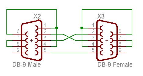
X2 – To project board
X3 – To PC or Terminal
From connector X2 you need to make a Pigtail adapter:
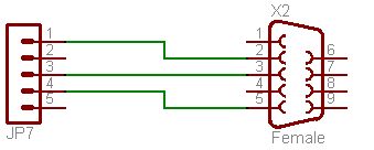
X2 PIN 2 connects to JP7/1
X2 PIN 3 connects to JP7/3
X2 PIN 5 connects to JP7/4 (Vss)
Port Configuration
Determine the serial communications port you are using and start realterm with the following command line parameters:
realterm.exe baud=9600 port=xx flow=2
or if you are using a different terminal use:
9600, none, 8, 1, rts/cts flow control
- Enable the setup mode by placing a Jumper on JP5 on the SET position
- A question mark <?> will show some help with the commands
- Power up the processor board and you will receive the following messages and follow the example shown:
Voltage Calibration
- Connect the DVM to the output of the PSU and adjust the output to the maximum output voltage e.g. 30.1V
- Type the command >vlt show
You will see something like the following on the terminal console:
0960 * 01000 = 960000 -> 960mV
The second value <01000> is the value you are interested in and this value may be changed to suite your needs.
Example:
- To adjust the display output to 30.1V take the following steps
- Divide 30.1V by 960 = 0.032533748
- Multiply the answer by 1,000,000 = 3253
- Type the comman >vlt set
- At the prompt enter the value e.g Value >32533
- Now type the <vlt show> command again to see the result.
Current Calibration
- Connect the DVM in series with a small load (e.g. 12V Globe) to the output of the PSU and adjust the output to limit the current value e.g. 500mA
- Type the command >amp show
You will see something like the following on the terminal console:
0162 * 01000 = 162000 -> 162mA
The second value <01000> is the value you are interested in and this value may be changed to suite your needs.
- Example:
- To adjust the display output to 500mA take the following steps
- Divide 500 by 162 = 3.086
- Multiply the answer by 1,000 = 3086
- Type the command >amp set
- At the prompt enter the value e.g Value >3086
- Now type the <amp show> command again to see the result.
Temperature and Fan
- Type the command >tmp show
You will see something like the following on the terminal console:
0395 – 0400 – 0001
The first value is the raw ADC value, the second is the temperature set point and the third is the value of the fan timer. You can adjust the set point value to suite the type of NTC Thermistor you are using.
- The fan must be set to “auto” for this setting to work by using the <fan auto> command.
- The fan will switch on when the ADC value is below the set point and switch off when the ADC value is higher than the set point and the fan timer has reached a pre set value. This will prevent the PIC controlling the temperature of the Thermistor to a pre set value.
- The timer value can not be adjusted – I have used <4096kb> program memory. However a US$69.00 license will remove the memory limitation and enable a future <4096kb> memory to code up to. Any enhancements will have to wait until I can afford the upgrade.
LCD Connection
JPL LCD ATM1602B Connections
RS to RB5 – PIN 38
R/W to RB4 – PIN 37
E to RB3 – PIN 36
DD0 to None
DD1 to None
DD2 to None
DD3 to None
DD4 to RD4 – PIN 22
DD5 to RD5 – PIN 21
DD6 to RD6 – PIN 20
DD7 to RD7 – PIN 19
Parts
The board may be used in various configurations and some parts are not required when an option is selected.
The PIC16F887 does not require the following parts:
Q7 – 4.0MHz crystal
C5, C6 – 22pF Ceramic Dipped Capacitor
The LCD Display Option does not require the following parts:
R4, R5, R6, R7, R8, R9, R10, R11 – 100R Resistors
R1, R2, R3, R13, R14, R15 – 3K3 Resistors
Q1, Q2, Q3, Q4, Q5, Q6 – BC557 PNP Transistors
LD0, LD1, LD2, LD3, LD4, LD5 – 7 Segment Displays
For some parts you need to calculate a value:
R22 – Current limiting resistor value for LCD Backlight
| Qty | Value | Device | Parts |
| 1 | PIC16F877A/887 | PIC Microchip | IC1 |
| 1 | 3mm LED | LED1 | LD6 |
| 1 | – | LCD Backlight | R 21 |
| 1 | 4.0MHz | XTAL/S | Q7 |
| 1 | 2K2 Calculate | .25W Resistor | R 22 |
| 6 | 3K3 | .25W Resistor | R1, R2, R3, R13, R14, R15 |
| 2 | 10K | .25W Resistor | R16, R19 |
| 1 | 10K | TRIMPOT | VR1 |
| 1 | 10uF/35V | Elect Cap Radial | C4 |
| 3 | 20pF | Ceramic | C2, C3, C7 |
| 2 | 22pF | Ceramic | C5, C6 |
| 3 | 100K | .25W Resistor | R20, R24, R26 |
| 8 | 100R | .25W Resistor | R4, R5, R6, R7, R8, R9, R10, R11 |
| 1 | 100nF | Ceramic | C1 |
| 1 | 330K | .25W Resistor | R 12 |
| 2 | 470K | .25W Resistor | R17, R18 |
| 2 | 680R | .25W Resistor | R23, R25 |
| 1 | BC548B | BC548B | Q8 |
| 6 | BC557 | BC557 | Q1, Q2, Q3, Q4, Q5, Q6 |
| 1 | DS275 | DS275 | IC3 |
| 1 | IPSC | 1X5 Socket | JP3 |
| 1 | LCD/LED | 1X3 Pin Header | JP4 |
| 1 | SET/RUN | 1X3 Pin Header | JP5 |
| 1 | RS232 | 1X5 Socket | JP7 |
| 6 | SA56-11SRWA | Kingbright | LD0, LD1, LD2, LD3, LD4, LD5 |
| 1 | TL081P | TL081P | IC2 |
| 1 | Ampron MF11 | Thermistor 10K | TH1 |
Lastly
Never give up hope. I destroyed 3 PIC Processors, 2 x 1.6A Fuses, 1 x 5V6 Zenner diode and one Fluke 630mA fuse while developing this project. I made three sets of PCB Boards and redesigned the 12/-12V PSU twice. I was ripped off when I purchased 20 bad quality 2200uF/50V capacitors. When I got stuck I asked for help and got it – thanks to Audioguru at electronics-lab for assisting me.
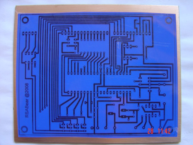
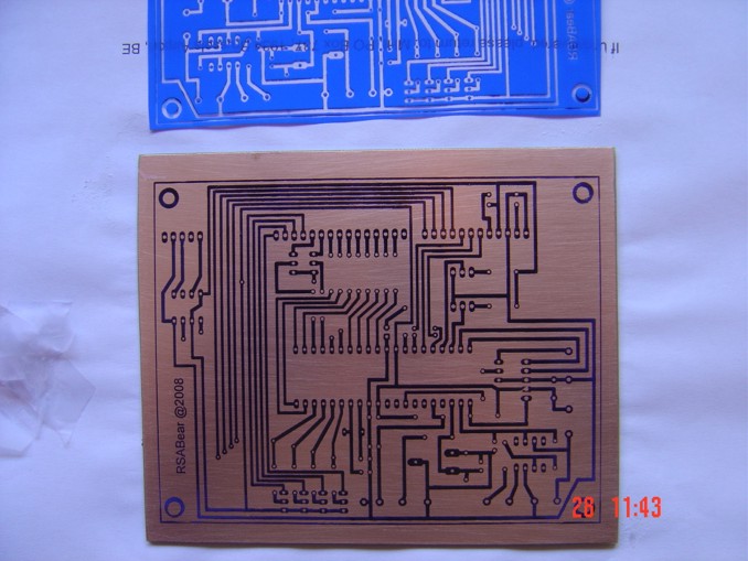
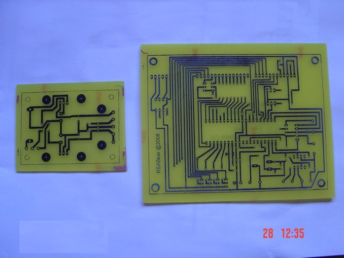
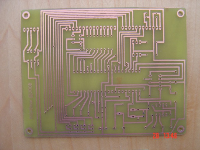
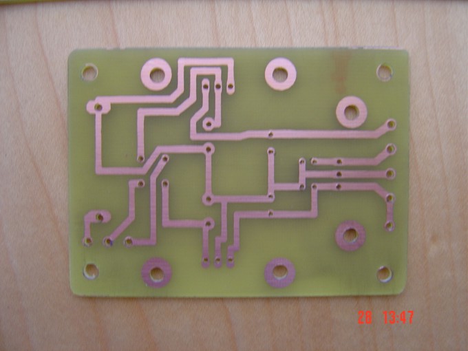
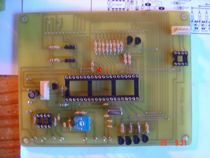
Photos
Please follow and like us:
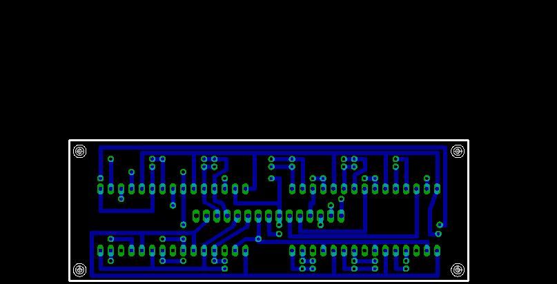
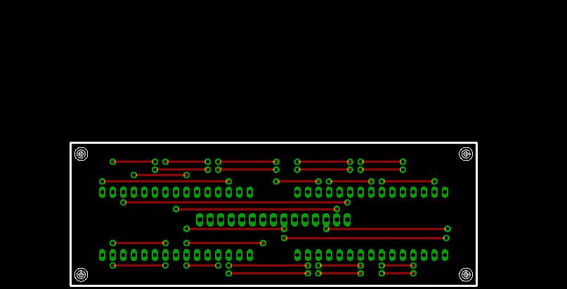
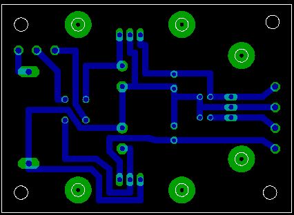
PCB


Hello, have you simulated in proteus 8.x this project?
Would like to use an LCD Display, do you have the circuit schematic?
You could send the project’s source, I use CCS 5.0 or XC8 or to have it in Spanish:
It cost, let me know.-
Thank you.-
Antonio.-