

89Sxx Development Board
- Dominikus
- ndom_dominikus@yahoo.co.id
- 16.702 Views
- advanced
- Tested
- 1 Likes

Single side development board with In System Programmable Flash based microcontroller, 89Sxx series.
Introduction
There are some 89Sxx development board, here is another one. I have designed this single side development board to be used as a tool for learning MCS-51 Microcontrollers, and for easy microcontroller project development.
The 89Sxx development board features :
-
89Sxx 40-DIL based design, 89S51/52/53
-
In System Programming (ISP) through the 6-pin header
-
RS-232 and RS-485 serial port (shared pin) for communicating with serial devices like PC
-
HD44780 compatible alphanumeric LCD connectivity with backlight control
-
4 on-board tact switch
-
16 general purpose IO port pins on 5×2 header (Port0 and Port2)
-
24Cxx I2C EEPROM
-
DS1302 serial Real Time Clock (RTC) with battery backup
-
On-board supply rectifier and voltage regulator
-
Single sided PCB design
Hardware
The hardware block is shown in Figure 1. The MCU is 89Sxx microcontroller. And the complete hardware schematic is shown in Figure 2.
-
Port1 is used as data-bus for LCD (4-bit interface, PCB lay-out for 16×2 character with backlight), on-board tact switch and connection for In System Programming (ISP)
-
Port0 and Port2 as general purpose IO, are available for interfacing external devices. Port0 is connected with DIP switch, and also P0.0 and P0.1 are connected with opto-isolated input
-
Port3, P3.0 and P3.1 are being used for serial communication UART, P3.2 for RS-485 control direction. P3.3 and P3.4 are serving as general purpose IO port pins. Another pins for communicating with serial chip, EEPROM, RTC and serial shift register (LED array indicator)
Figure 1. Hardware block of the 89Sxx Development Board
Figure 2. Schematic
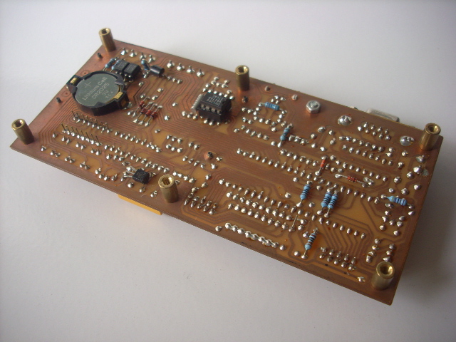
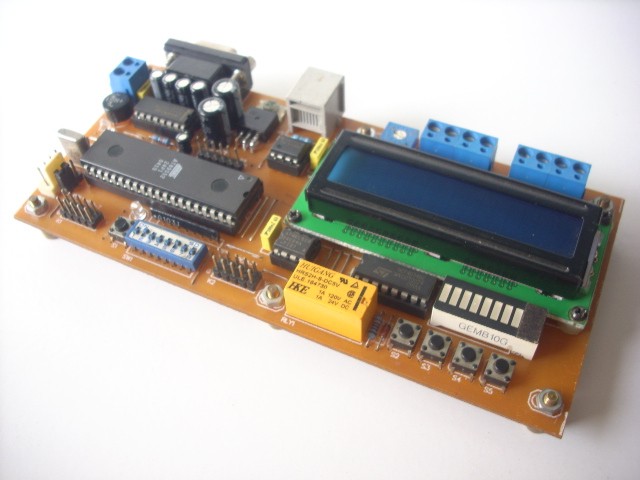
Figure 3. Hardware
Figure 4. Printed Circuit Board
A SPI In system Programming adapter should be used for programming the circuit. Connect the ISP adapters 6 pin connector with the 6 pin ISP header on this board. Please note with the connection order (may a little bit different).
Example project … 89Sxx based SMS Controller
The project shows 89Sxx Development Board for remote control and monitoring. The system consists of 89S52 as main processor and mobile-phone (GSM modem) for remote control or monitoring over cellular network.
Features of the system are as follows.
Features of the system are as follows:
-
8 ch input (Port0) and 8 ch output (Port2)
-
auto-send message on input changing/alarm, input changing mode : LO-HI, HI-LO
-
switch output command by group or independently
-
status request parameter by sending SMS command
-
download some simple text script for time programmable output
This circuit connects to the serial port featured by many cellular phones. Its function is to provide an input and an output port capable of being remotely controlled using another mobile.
Control takes place by means of sending SMS (Short text Messages Service). When the mobile receives a predefined text message, the circuit automatically recognizes it as a command, and switches the output accordingly.
The device can be used to notify the status of the input port, sending automatically a message every time the input changes. To know input status at any time, the device can send back a SMS describing the status of the input, as a response to a request message.
Communication between board and mobile-phone (modem) : rxgsm (P3.3 , RX from gsm), txgsm (P3.4 , TX to gsm) in TTL level. To start interfacing with, similar to modems, GSM cellular phones can accept AT commands(more precisely an extension of the AT command set).
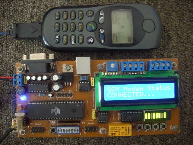
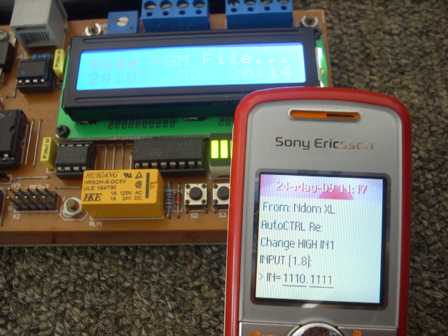
Figure 5. SMS Controller Project
Please follow and like us:


Subscribe
Login
0 Comments


")

