
LED UV exposure box
- Bogdan Raducanu
- http://www.electrobob.com
- bogdan@electrobob.com
- 57.269 Views
- medium
- Tested
- 0 Likes

Introduction
I have been using the toner transfer method for about 9 years with great results. Occasionally I would need a board with finer traces and I would use UV method. My exposure setup allowed only a single sided board to be made and it was composed of a 30cm UV tube, some holders, a table, board and film. Exposure time was rather long as the tube was far away from the board.
A few months ago I was looking for some LEDs at one of my suppliers and found that the also had UV LEDs. My mind went directly to upgrading my not so great setup, so I began looking on the internet for info. It turns out some other people have done it, and this instructable confirmed it was really possible. A LED UV box has a clear advantage over a tube one: it can be made in any size, depending on the needs.
I bought 25 LEDs and began to experiment. This way I was able to find a compromise between LED density (spacing), distance between LEDs and board and cost. I wanted something compact, I don’t make large PCBs and those 30cm tubes were not right for this job.
Note: Don’t look directly into the UV LEDs. It may harm your eyes.
The LEDs
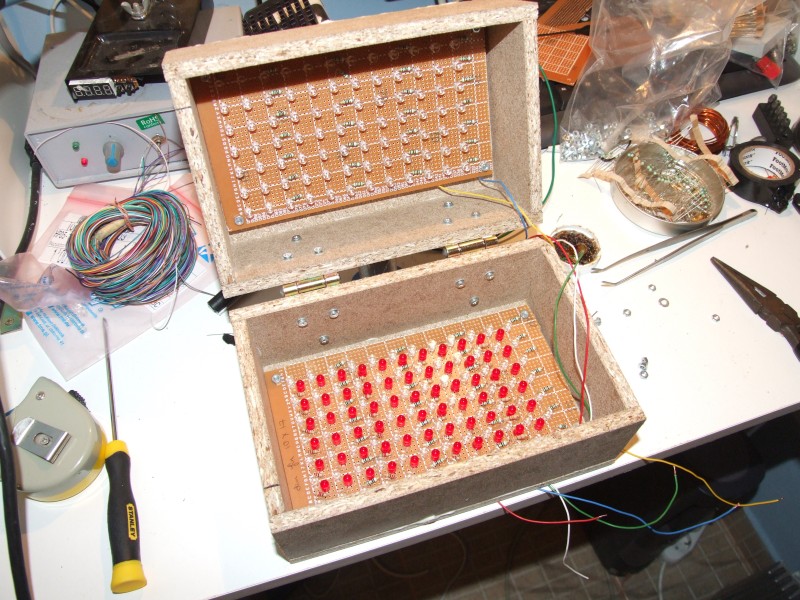
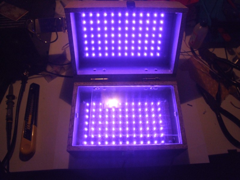
The LEDs are OSSV53E1A from OptoSupply and they have an 140° angle. This means that the first plane with uniform density can be obtained at a shorter distance from the LED, for a given spacing between LEDs which means smaller height for the board. Their peak wavelength is 405nm, which is higher than recommended by the boards’ manufacturer. Results showed they emit sufficient UV light in the responsive spectrum of the photo resist to allow for a perfect exposure.
I wanted to use a common voltage so 3 LEDs in series with a 91Ω resistor are connected to 12V to ensure a 20mA current.
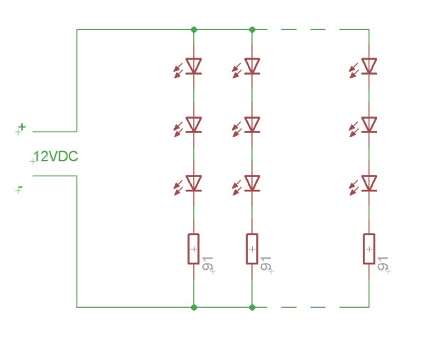
The final setup will contain a LM317 for stabilizing as I don’t plan on using my variable regulated supply all the time. There is another reason for this, due to the non linear nature of the LEDs, varying 12V with +/-5% creates much larger current variations which influences the required time. Putting a regulator on the box simply allows more flexibility in choosing the power supply.
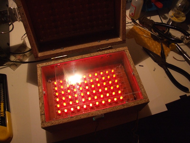
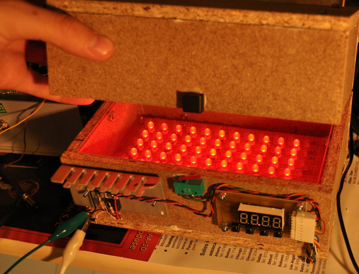
On the bottom board I have added red LEDs. These LEDs help me align the top and bottom films. I have used low brightness, cheap, matte LEDs as I have to look into them when aligning the films. Connection is similar, 3 LEDs in series with a 220Ω resistor, except for the last row which contains 2 LEDs and a 330Ω resistor. These are not really necessary, aligning the films can be done in a dim ambient light.
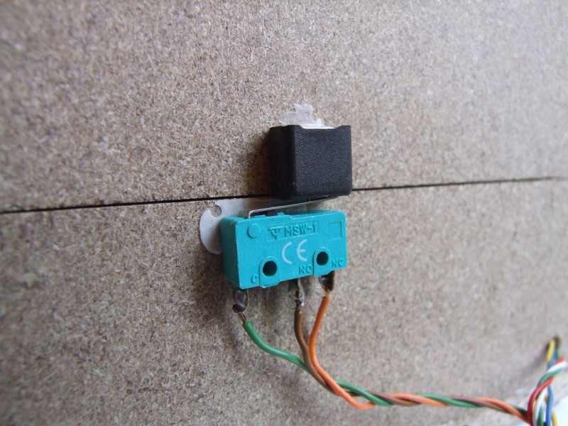
For safety reasons and extra functionality I added a switch to turn off the UV light when the box opens, turn on the red light and stop the timer. This makes the box more high tech and gives it a professional behavior.
LED spacing
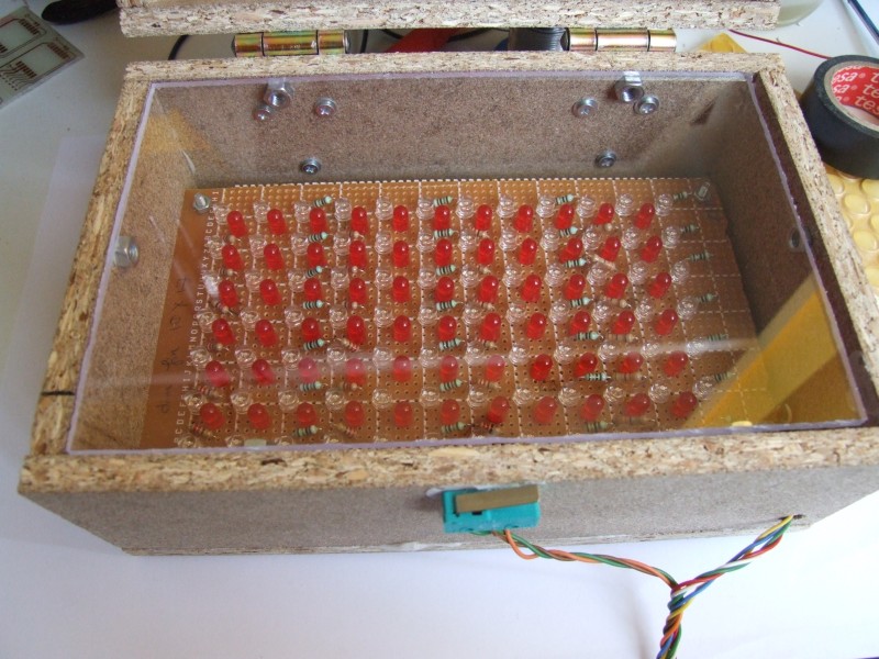
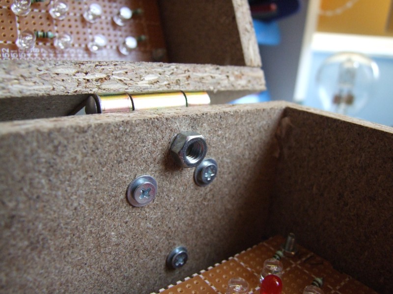
I used nuts glued on the interior walls of the box to hold the bottom 4 mm thick plexiglas panel. The choice was simply of what was easily available: nuts. Don’t use normal glass as it blocks ultraviolet light. There is no top panel mounted, because it is part of the aligning procedure: I put the first film on the bottom, then the board and the second film is taped to a smaller piece of plexiglas. Aligning means aligning the smaller piece of the plexiglas so that the two layers overlap perfectly. Having the film attached to it makes it easier. Extra markings outside the board help this (ghost vias). Part two should contain a more detailed tutorial on making double sided boards.
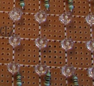
The final assembly allows an area of about 10x15cm of board size, with the interior dimensions of the box being 18cm long, 11cm wide and 5.5cm deep for each of the two halves. Exterior dimensions will depend on the thickness of the material used. Each board contains 7×12 UV LEDs, with 3 and respectively 4 holes between them( the actual spacing between the center of the LEDs is the same). The distance between the top of the LEDs and the board is 3.5cm, including the 4mm plexiglas panel. Check out the detail below to see the LED arrangement on a normal 0.1″ or 1.27 spaced board:
Exposure
Exposure results: I tested with a small board from 2 minutes up to 8 minutes. Starting with the minimum of 2 minutes proved not to be the best idea, but my long exposure time old setup made me choose this value.
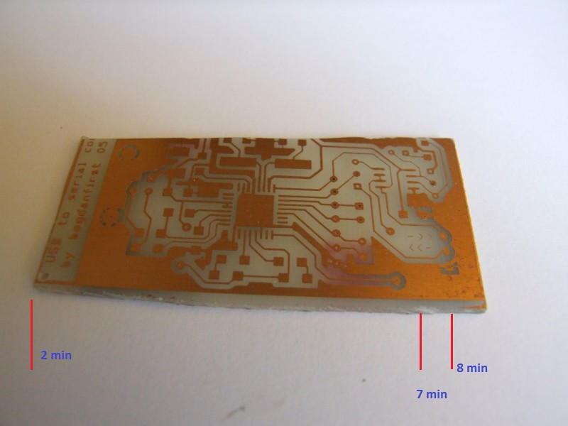
What you can see in the picture above, from 2 to 7 minutes exposure if perfect. At 7 minutes some over exposure starts to show up, only in large copper areas, due to the fact that the film was printed with a laser printer. This result is very different from what I have obtained when using a fluorescent tube: below 12 minutes it was clearly underexposed and above 14 it was clearly overexposed, leaving only a small interval where it was right.
So far I have made 4 boards with 2 minute exposure and they came out perfect. When free time will be available I will investigate what the results are for less than 2 minute exposure. As any time between 2 and 7 minutes seems to work, there is no immediate need for a timer. Still, part two should contain a basic circuit for this.
Gallery
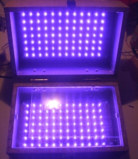
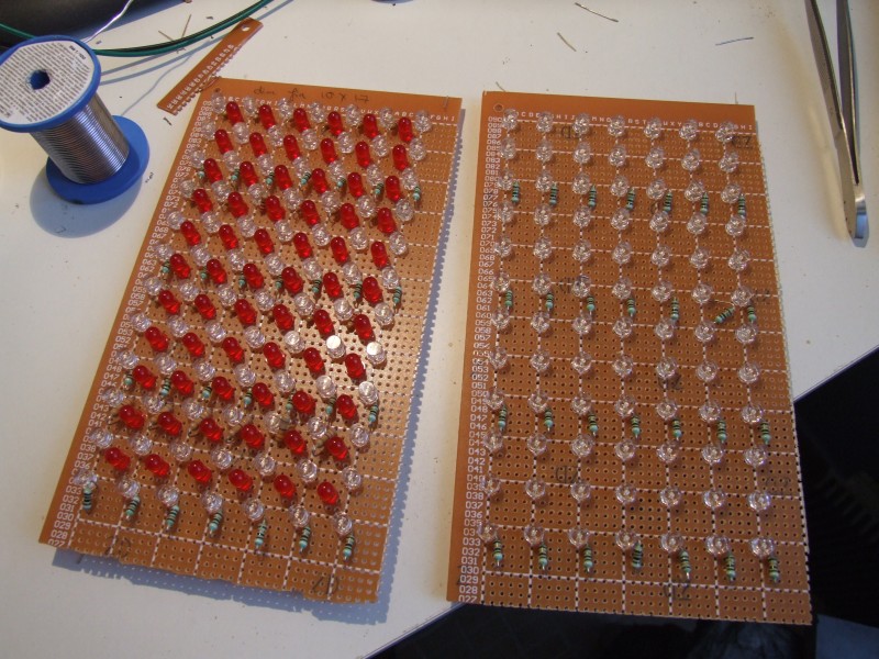
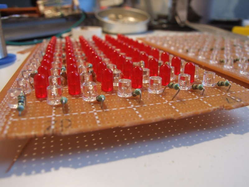
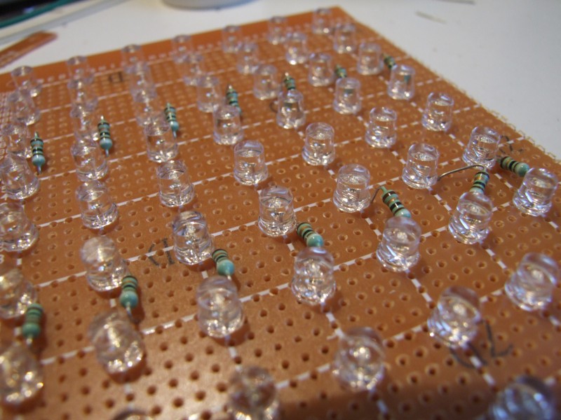
The finished panels:
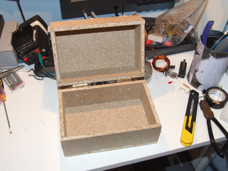
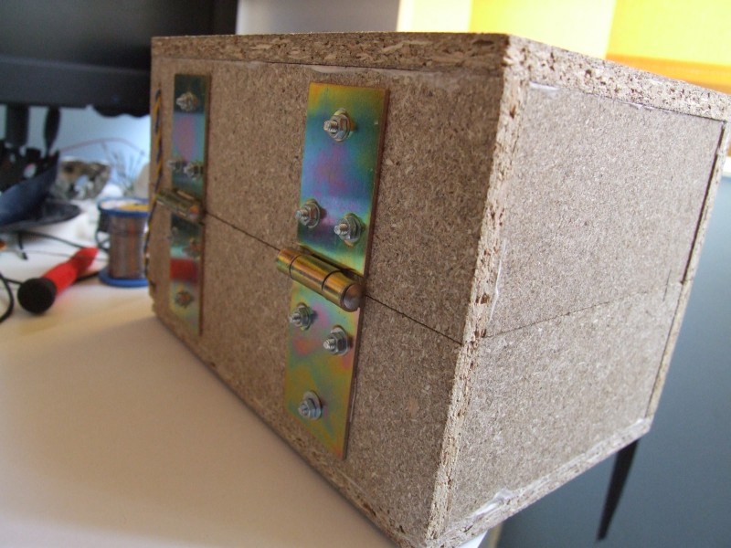
The box:
Panels installed:
Bottom plexiglas panel installed and a nut:
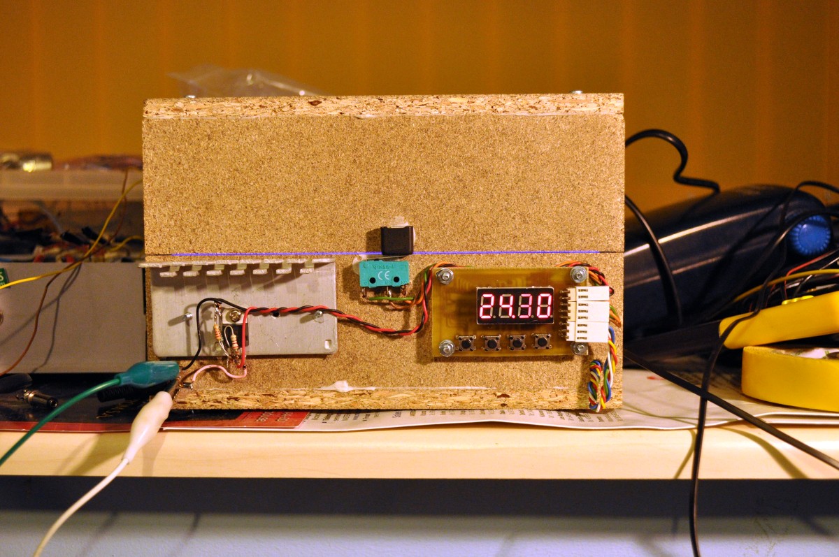
The back:
The safety switch:
RED on:
UV on (switch is not used):
Build your own
To build your own you first must decide what the required size is for you. With my setup, boards up to 10 x 15 cm may be exposed. For this, you will need the following materials:
- 168 UV LEDs, OSSV53E1A;
- 56 91 ohm 1% 0.25W resistors(5% is also ok);
- 66 red diffused LEDs;
- 18 220 ohm resistors for red LEDs;
- 6 330 ohm resistors for red LEDs;
- 2 prototype boards, 13 x 25 were the smallest size I found that fitted;
- 1 switch for the lid capable of 1.5A minimum;
- 2 hinges;
- 1 box;
- misc: screws, nuts, glue etc.
The box may be made of your choice of material. I’ve built it out of two identical halves, with interior dimensions 18 x 11 x 5.5cm each. The material is 8mm thick OSB, for which you will require the following parts:
- 4 11 x 5.5cm pieces;
- 4 19.6 x 5.5cm pieces;
- 2 19.6×12.6cm pieces.
The timer
Continuing the development of my UV exposure box I have designed and built a countdown timer.
There are a few others out there for the same purpose, but I wanted to add some more features to make things better.
As I have mentioned in the previous post, safety was a big concern for me so I added a switch that should prevent turning on the UV LEDs when the lid is open. Of course, this is not enough, so the switch has to work along with the timer ensuring that everything goes smoothly.
The key features that I wanted:
- Exact time display
- Adjustable time, 10 second resolution
- Start/pause function
- Automatic pause and UV LED turn off when the lid is open
- Some predefined available values for easy access.
Implementing the safety measures is easy, as the switch on the box could be made to connect either the RED or the UV LEDs. The timer needs to control the UV LEDs, so I have used a MOS transistor. It also needs to know the state of the box lid. I have built a circuit that can achieve all this. The concept schematic can be seen below:
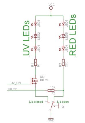
The schematic shows, symbolically, the red and UV LED arrays through the basic cell that is repeated on the panels: a series of three LEDs and a resistor. As you can see, there is no way to turn on the UV light when the lid is open, even if such a command would come from the microcontroller. The microcontroller can turn the UV light on via the MOS transistor only when the lid is closed. This is controlled through software too. In order to sense whether the lid is open or not, the microcontroller monitors the state of the cathode of the red LED array. When the lid is open, this is shorted to ground and the micro sees a low logic level. When the lid is open the red LEDs will conduct current and force the microcontroller to see a high. This current is small, limited by the 10K resistor and therefore the LEDs do not appear to be on. I could have chosen to leave the red LEDs on all the time as this does not influence the functionality of the exposure box, but it adds extra consumption and more heat needs to be dissipated by the lower panel.
Although it is not totally justified, I decided to go the full effort and make this timer with a display. There could be many more ways to do this starting from a simple 555 circuit. I wanted the circuit to be a challenge for the box itself, so small SMD parts are used wherever possible.
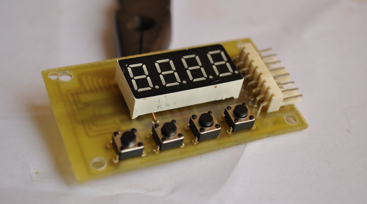
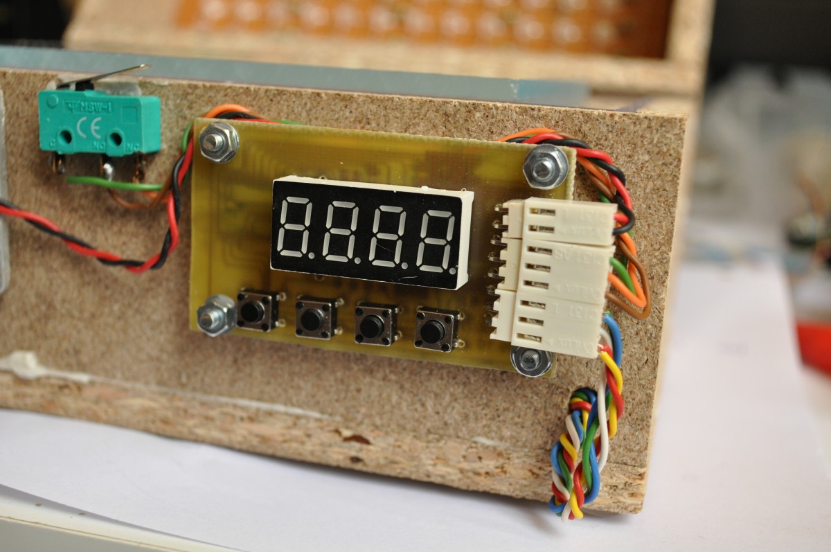
The display is a KW4-361ASB from Luckylight. It is small, 9mm digit height and has 4 multiplexed digits. There were two basic criteria for selecting this particular part, first I wanted it to be small and efficient so that a small current is enough for a bright display and second I wanted it to be multiplexed as this simplifies board layout.
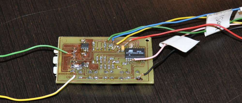
I choose an ATTiny2313 microcontroller as it has all the features needed to implement all the tasks: sufficient pin driving capability, a timer, enough pins and memory. It’s got an internal oscillator too, but as I missed it, the tolerance is within 10% which I consider too high for this project. I have later added a crystal on the board but adjusted the starting timer value on my particular circuit to compensate for the internal oscillator deviance. This was easy as I knew that the refresh frequency for the display should be 50Hz, so a frequency meter was all that I needed. I believe that this should not fluctuate and no future compensation will be needed to maintain the error at a small value, maybe less than 2-3%. I do suggest using a quartz crystal, but this is not mandatory, you may use my method or simply accept the maximum 10% tolerance.
To turn on the UV LEDs I have used a TSM2302 MOS transistor which has a capability of 3.6A, more than enough for both the boards. Other transistors may be used, such as IRLML0060TRPBF.
Other than this, there are 4 buttons on the board, a 7805 regulator and connectors. The 4 buttons have the following functions, from left to right: START/STOP the timer, UP adds 10 more seconds, DOWN subtracts 10 seconds, MEM recalls some preset values from the memory.
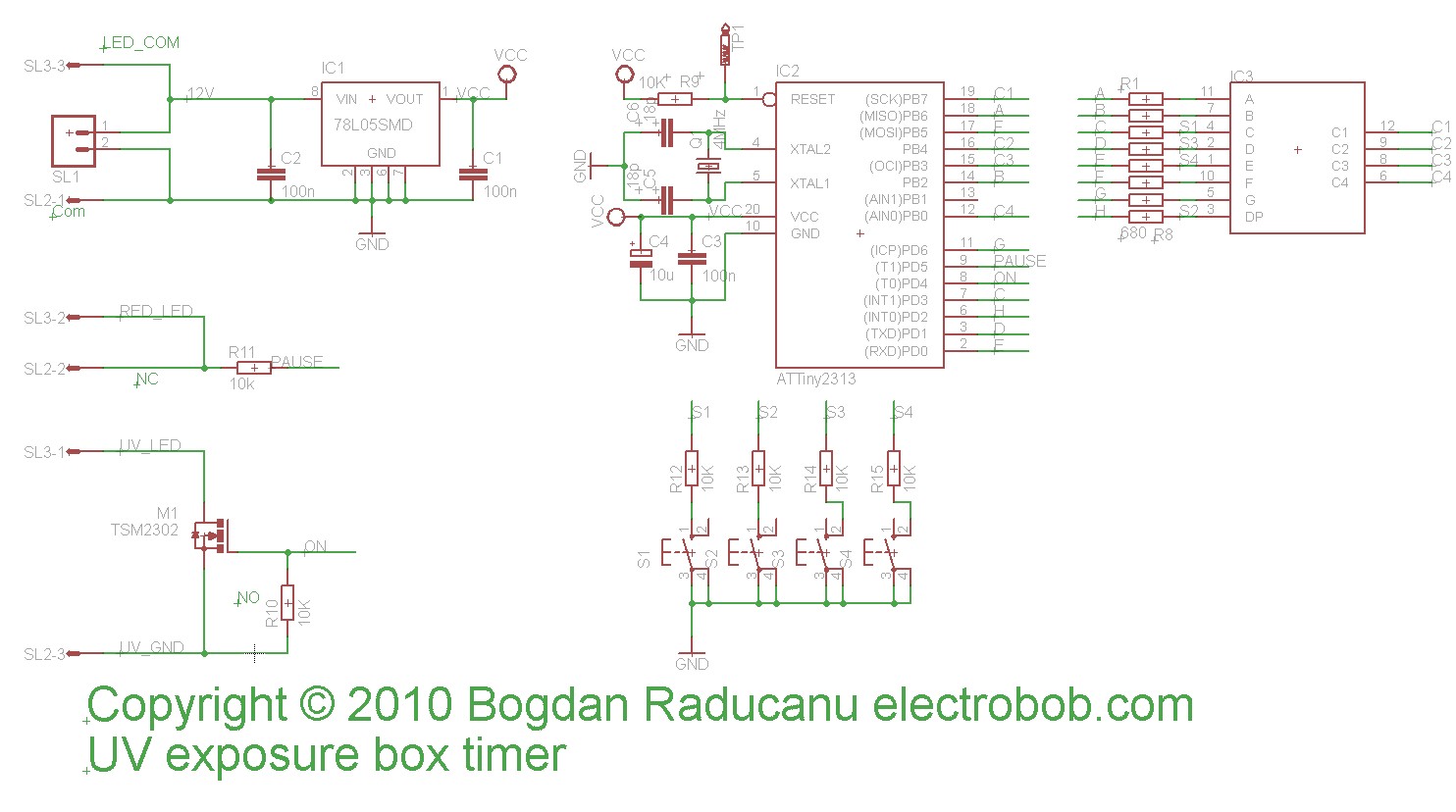
Because software allows flexibility in connecting the display, I chose to make the connections as easy as possible for the PCB layout, and this is why the schematic is not very straightforward.
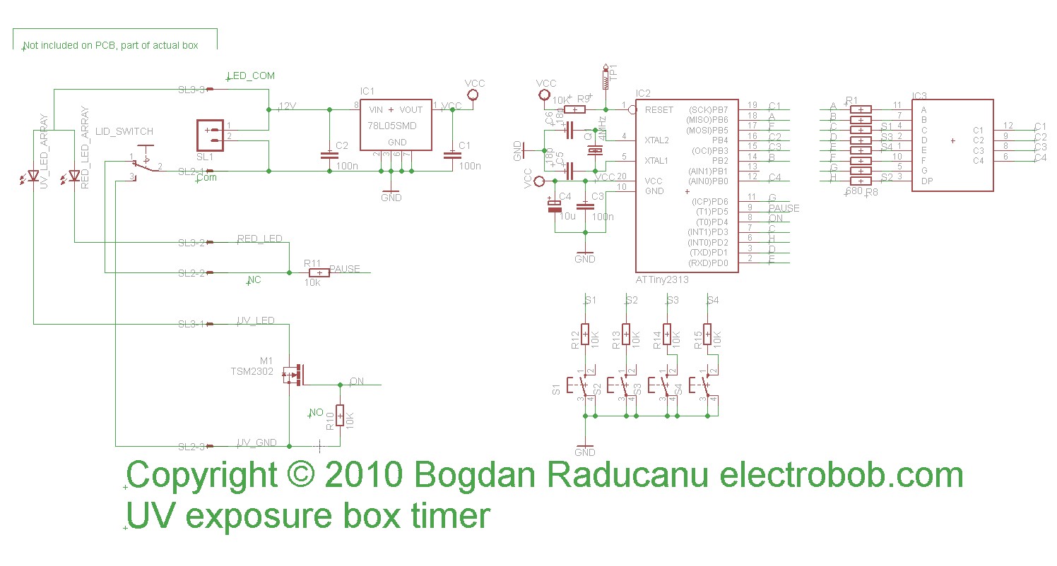
The connection of the lid switch and LED arrays is shown below:
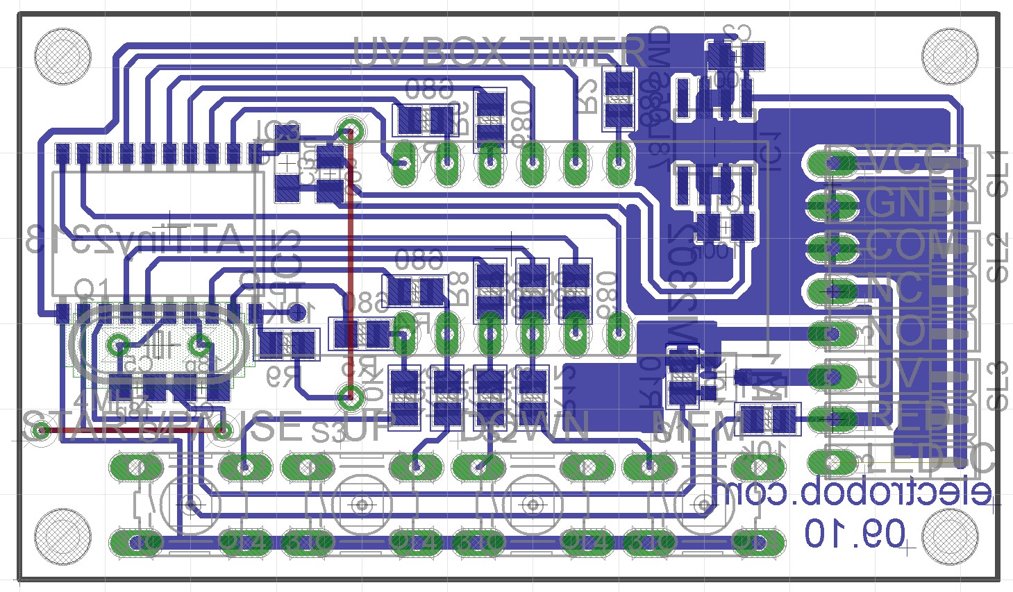
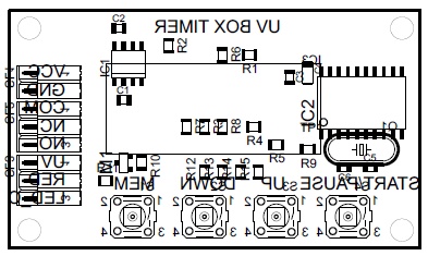
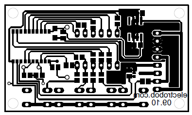
Because the box was functional, I decided to make the PCB a challenge for it: Small display, small SMD components. The finished PCB is shown below, the board is very compact and measures less than 6×3.5cm:
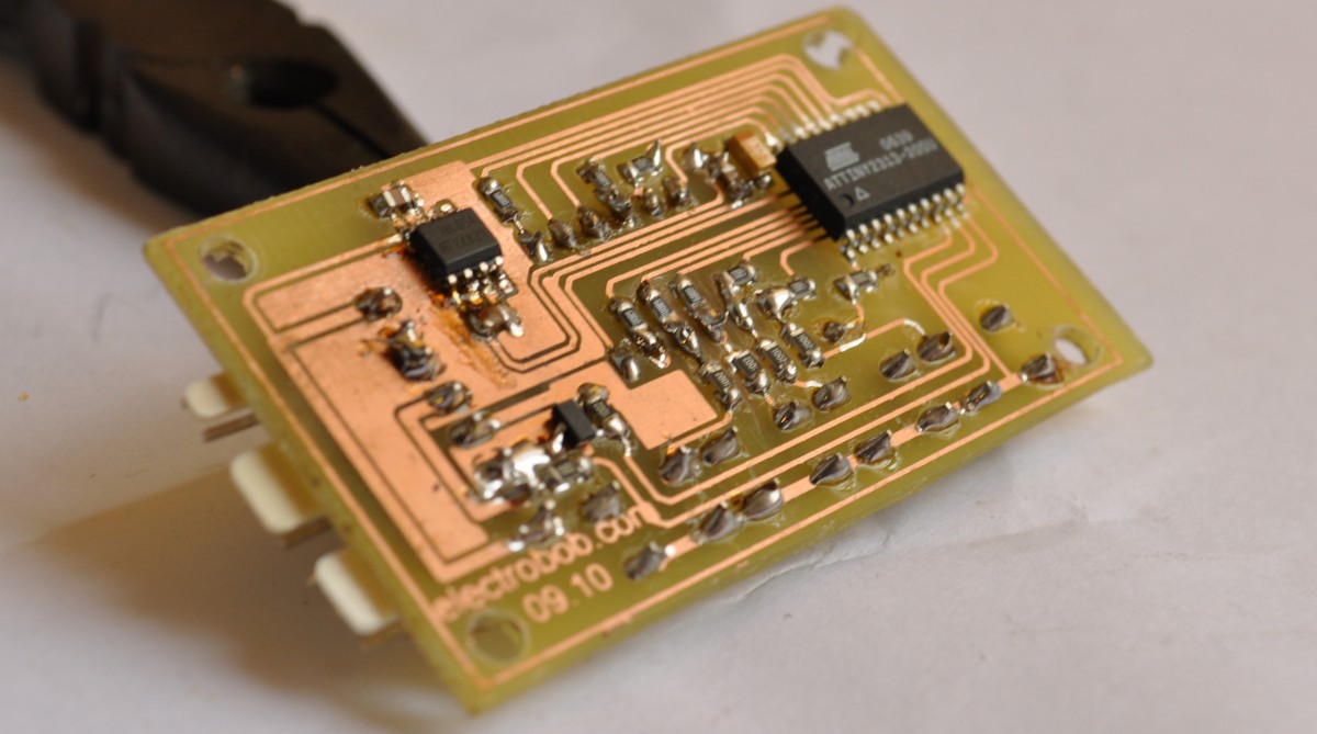
You may wonder why there is no programming connector. The reasons are two: I wanted to make it as compact as possible and the fact that it is the type of circuit that requires a single programming (For the end user). As all the pins required for programming are connected to the display it is easy to connect a few wires to the programmer, as you can see I did in the picture below:
The finished timer:
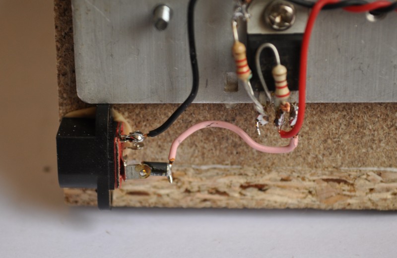
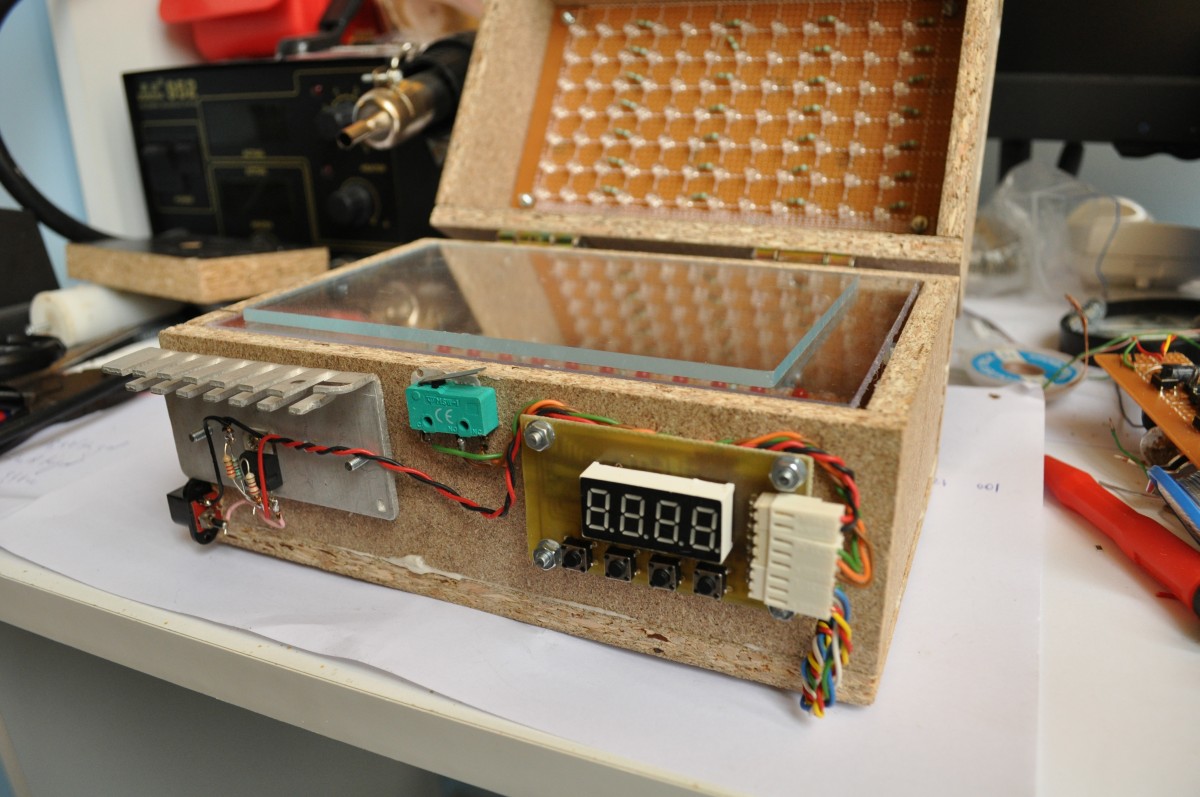
LM317 voltage regulator and heatsink also mounted on the box:
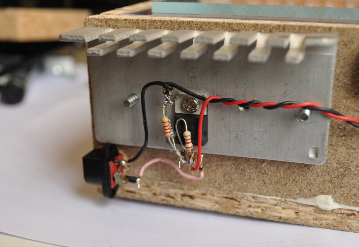
I’ve used 2 nuts on each of the mounting screws between the heatsink and the box to ensure good air circulation:

And, of course, a 3A protection diode, just in case:
The mounted timer:
The final result:
First test:
Checking the safety measures, red turns on, UV off, timer stops:
Please follow and like us:
PCB


Hi,
I want to know how the connections of the LED are made under the board ?Can you sent me a picture of it. Thanks
The LEDs are connected in sets of 3 with a series resistor as you can see on the schematics above. This set of 3 LEDs/resistors is repeated to fill the entire board.
I’m a complete newbie to programming, and am wondering if there’s a version of your code available for Arduino? I tried reading the .c file, but it’s more complex than I’m capable of understanding.
We are sorry, this project is based around ATtiny2313 and we don’t have Arduino code.
I made this project but the timer has a problem. The LED display keeps blinking alternating the digits in sequence. It counts but the counting time is not correct. The last digit on the right side decreases but it takes quite some time, 20 seconds or so. Can you give me an idea of what the problem might be?
Thanks
Sacramento
My timer has a problem the same.
Code error!
I am a complete rookie/newbie at electronics and I can use all the help I can get. That being said, would you send me or publish the parts list for the timer? Mainly the size of the SMD parts, ie the resistors. I can go through your write up and make a list of the big stuff. Also a photo of the underside of the circuit boards with the led’s would be nice. I have an AVR USB Tiny Programmer, will that work, and do you have a better picture or a guide to show how to wire up the timer to be programmed using this, if this will indeed work?
Some years ago I made an exposure tray with UV leds, much like the here proposed.
true the pointing effect lighting of the leds the system dfoes’nt works100%, some things are over-exposed other underexposed.
I placed a frosted glass for the leds and it was OK, I think that in your case it will be the same.
what is the total cost to make this?
An estimation of the cost is about 80-100 USD
Ok this is usful Project for me. Thanks