
Arduino Solar Day Night Controller
- Garrett Fogerlie
- elite_installs@hotmail.com
- 16.199 Views
- easy
- Non tested
- 0 Likes

Introduction
This is an Arduino controlled light sensing switching unit. Its main use is to control solar lights to turn on when it is dark outside, but it can work in many more applications. This guide will walk you through every aspect of the building process. Prior knowledge of the Arduino unit is not necessary since the code and schematic have been supplied for you. This project would be fairly complex to build without an Arduino; it is a good example of how a microcontroller can make a circuit far less complex, with less hardware trial and error.
Specs
- Input Voltage Range: 7 to 18 Volts DC
- Switching Power: 3 Amps*
- Light Range: Variable, Very Bright to Dark
*Adding a Relay can greatly increase the switching amperage.
Explanation
This project has three main sections, the Arduino unit, the software, and the circuit.
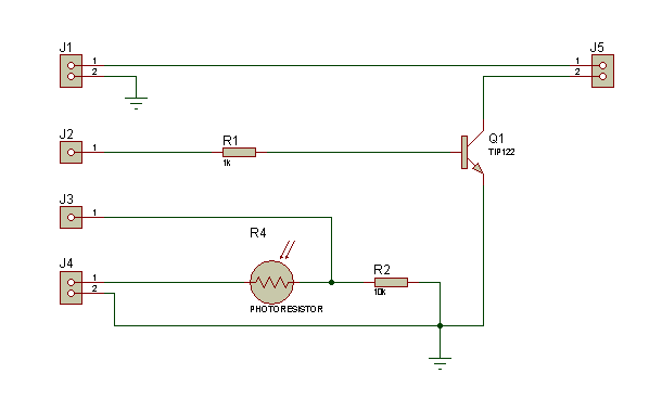
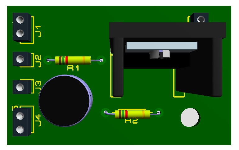
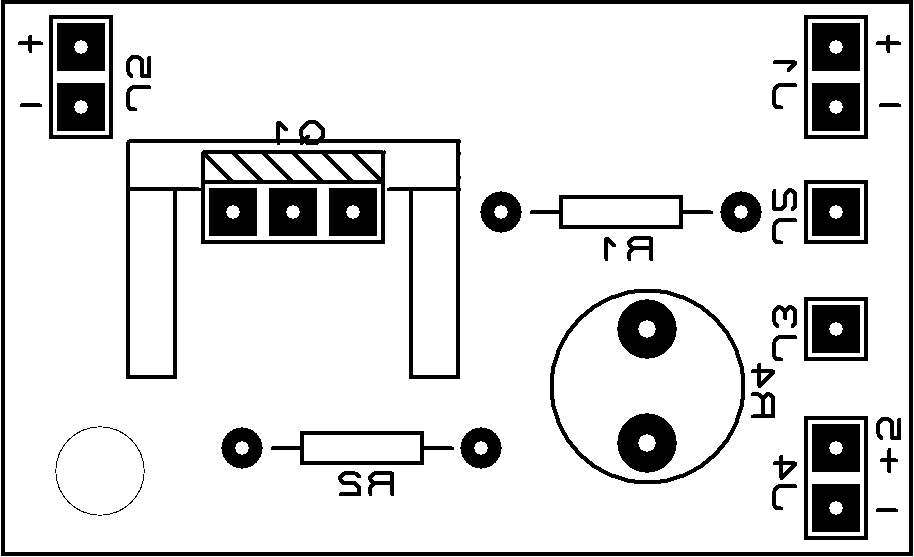
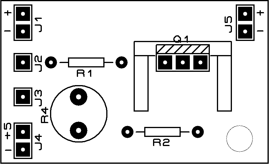
The Circuit is composed of two sections, the light sensing and the power switching. The light sensing part consists of a photo-resistor R4, connected like a voltage divider to R2. Since the resistance of the photo-resistor changes depending on the amount of light that is shining on it, the voltage divider’svoltage ratio changes depending on the amount of light present. The voltage going through this part of the circuit is 5 volts dc, supplied from the Arduino board to J4 of the circuit. So the voltage divider is dividing the voltage between the maximum 5 volts, to the minimum 0 volts. The Arduino senses this voltage on its “Analog Pin 0” that connects to J3 on the circuit. This is called “analogRead,” it divides the 0 to 5 volts by 1024 (10 bits, or 2^10) so it can sense a change in voltage as small as .0048 of a volt.

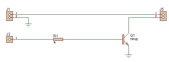
The power switching section of the circuit is quite simple; it uses a NPN switching transistor Q1, that is digitally controlled by the Arduino board from ‘Digital Pin 3’ connected to the circuit through J2. It switches the negative leg of the supply voltage from J1. J5 is where a low voltage light or anything you want turned on and off is connected.
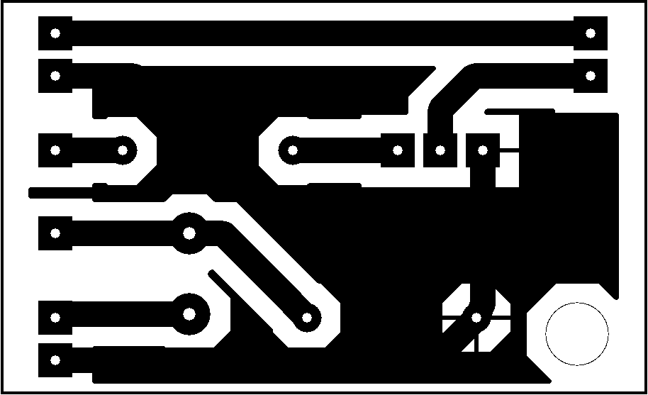
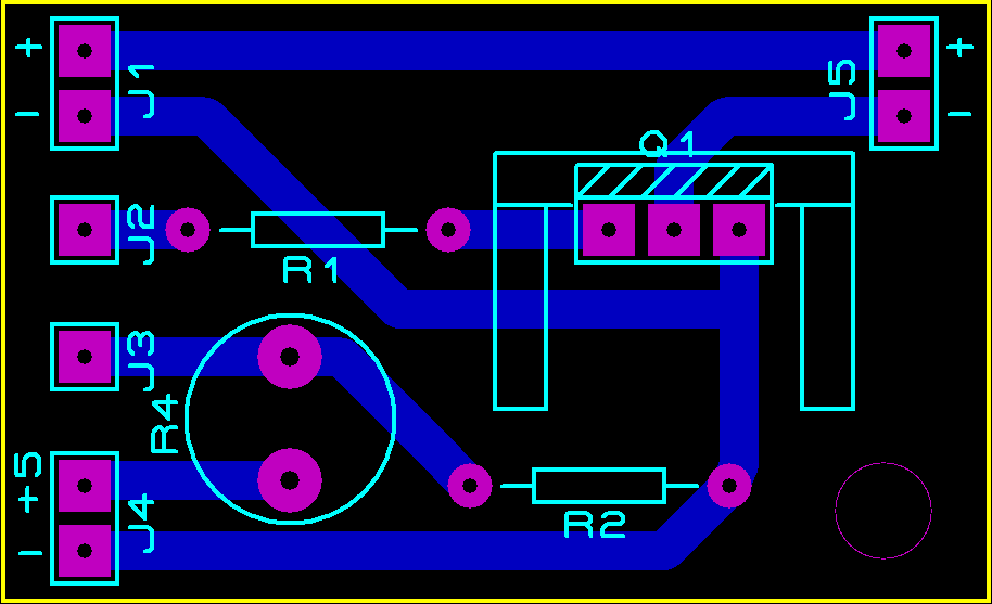
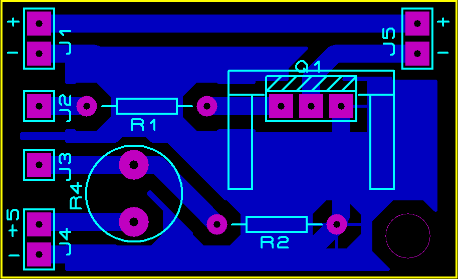
here is no R3 on the schematic, my apology I labeled the photo-resistor R4 on accident, sorry. I included two different PCB bottom copper designs, one has a ground plane and the other does not. Use whichever you prefer.
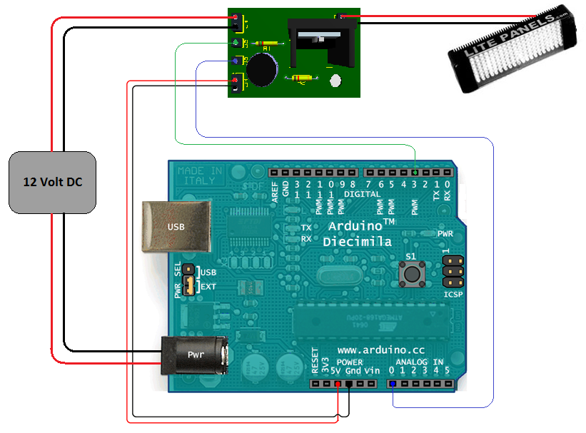
I won’t go into the parts of the Arduino, mainly because it is already a well-documented unit. The picture at the top should make it fairly obvious to see how it is connected. The main thing to look out for is the PWR SEL jumper between the USB and the PWR connector, needs to be switched to EXT, if it is not powered from the USB. If there is something you don’t understand, you will get much more help from their homepage:http://arduino.cc/en/Guide/HomePage
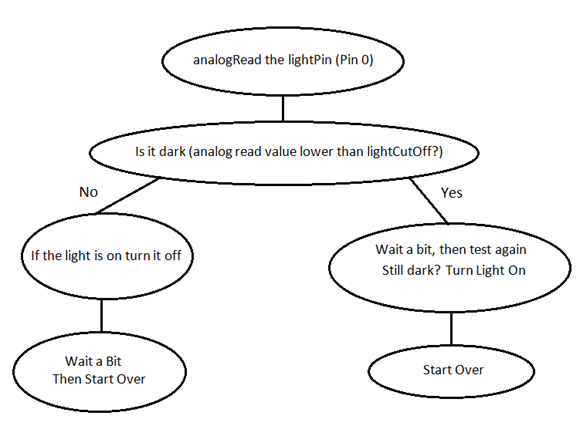
The software is in a zipped folder called ‘Code.zip‘ and it works like this:
Parts List
| Quantity | Reference | Description |
| 1 | R1 | 1k Ohm 1/8 Watt Resistor |
| 1 | R2 | 10k Ohm 1/8 Watt Resistor |
| 1 | R4 | Photo-Resistors (276-1657) |
| 1 | Q1 | TIP122 Darlington Transistor |
| 1 | . | TO-220 Heat Sink |
| 1 | . | Arduino |
Helpful Links
-
Voltage Divider Info http://en.wikipedia.org/wiki/Voltage_divider
-
TIO122 http://mediastudy.buffalo.edu/Robotics_Inventory/sheets/TIP120.pdf
-
Photo-Resistor http://www.radioshack.com/product/index.jsp?productId=2062590
-
Arduino http://www.arduino.cc/
Please follow and like us:
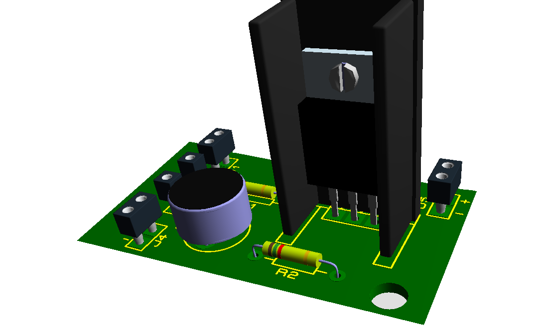
PCB


Nice to meet you,
I am reading the site: https://www.electronics-lab.com/project/arduino-solar-day-night-controller/
I understand most explanations at this site but don’t find where or how to purchase the PCB’s or the whole kits, PCB’s and components.
Thank you.
Claude
It’s because we don’t sell kits on our website but you may find kits of our projects on http://www.koteq.com
Just use a prefboard