

MultiKey – One Wire Keypad
- Rui Cabral
- http://www.ruijc.webnode.com
- rui.j.cabral@googlemail.com
- 10.161 Views
- easy
- Non tested
- 0 Likes

Introduction
This is a simple and easy to make serial keypad. The microcontroller will output the number of the push button pressed.
This project can be used for many different purposes. Probably the most used application would be to interface to any electronic project that requires a keypad. There are several ready made keypads on the market, but those work with matrix connections and require 7 pins for a 12 button pad. For new programmers, matrix keypads can be a bit tricky to program.
My circuit can use from 4 up to 12 push buttons with only one wire connection ( plus ground pin ) making possible to use a small microcontroller like an 8 pin to use this keypad. It’s also built in a setup mode where it’s possible to change the key output rate. This setting is saved in the microcontroller’s memory.
Another use for this is to, for example, connect to the computer and use it to control applications or even games.
Using any RS232 to keyboard software it’s possible to assign the input signals and convert them to keystrokes.
Schematic
The schematic shown bellow is for the 5 button version.
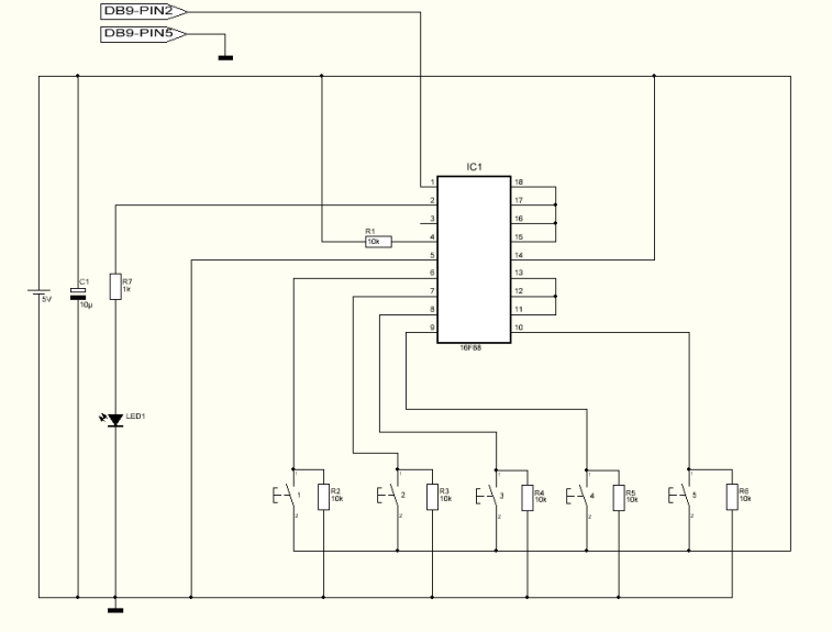
Notice that pins 11,12,13,15,16,17 and 18 are connected to ground. For each button added just remove the ground connection and connect the pin to a push button and add the resistor the same way as the first buttons.
Parts List
R1 10K ohms resistor
R2 10K ohms resistor
R3 10K ohms resistor
R4 10K ohms resistor
R5 10K ohms resistor
R6 10K ohms resistor
R7 1K ohms resistor
C1 10uF capacitor
Led1 SMD green or red led
IC1 16F88 microcontroller from Microchip
S1 Push button
S2 Push button
S3 Push button
S4 Push button
S5 Push button
Others:
Box
DB9 connector
PCB
Hex program for the microcontroller
For 12 push button version:
R8 10K ohms resistor
R9 10K ohms resistor
R10 10K ohms resistor
R11 10K ohms resistor
R12 10K ohms resistor
R13 10K ohms resistor
R14 10K ohms resistor
S6 Push button
S7 Push button
S8 Push button
S9 Push button
S10 Push button
S11 Push button
S12 Push button
How it works
For the first time I recommend to connect it to any pc and using the terminal program select 9600 Baud, no parity, 8 for byte size and 1 stop bit. These are the settings for both pc terminal or receiver microcontroller. To enter the Setup mode the S4 button should be pressed and held when turning the power on. The led starts to flash and S1 is used to increase the rate while S2 is used to decrease the rate. The minimum rate is 10ms and the maximum rate is 2550ms. It will increase/decrease 5ms each button press. Pressing and holding S3 will test the setting and will display the rate speed both on led and RS232. Button S4 will save the setting into microcontroller’s memory, exit the setup mode and enter the normal mode. In normal mode, when pressing one of the buttons it will flash the led and output the corresponding button number via RS232.
Hex Programm
The Hex program named Multikey must be saved in the device’s memory ( 16F88 )
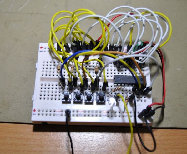
Testing
I’ve assembled the minimum button setup ( 4 buttons ) on a breadboard and connected directly to my PC RS232 port. I didn’t use any level converter, such a max232, because it normally works very well without it. In some cases it’s required to have the level converter. Turned the power on and pushed the buttons. The output was too fast so I turned the power off. I turned on the power again but this time i entered into setup mode. Increased the rate to 200ms and saved the setting. Tested again and now I get a good response.
Please follow and like us:
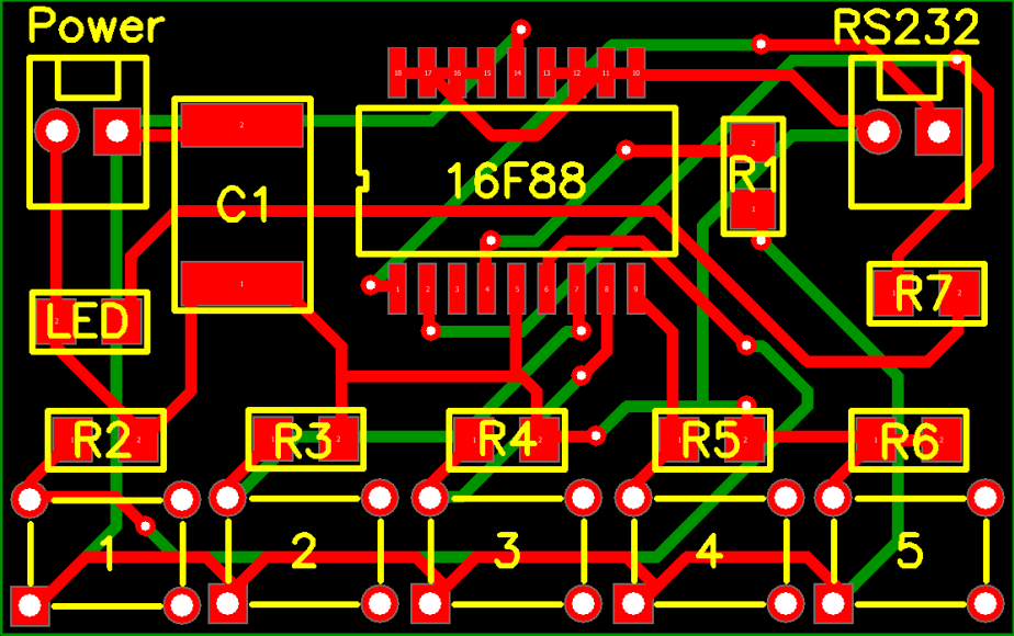
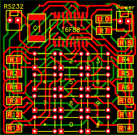
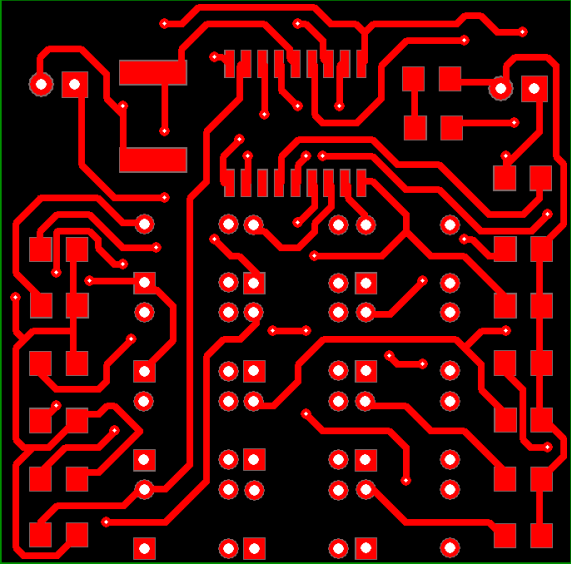
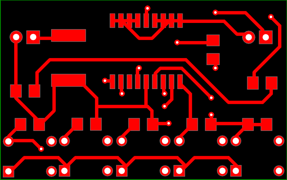
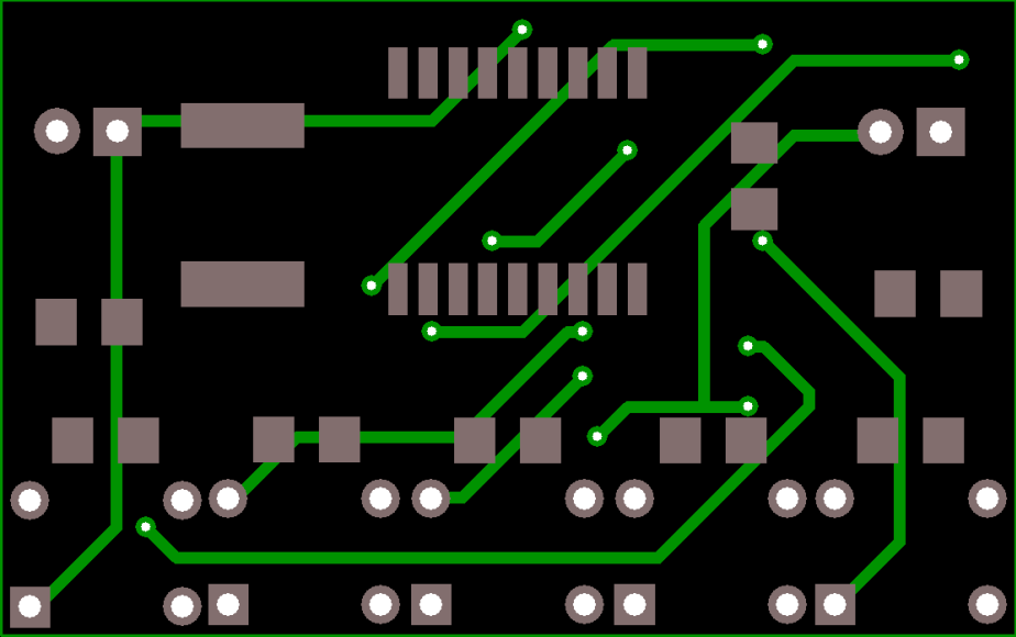
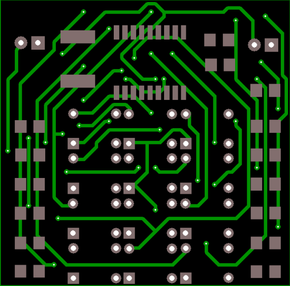
PCB


MR. BROTHER, PLEASE SEND ME CODE IN EMBEDDED C OR KEIL SOFTWARE ZIP FORMAT. REGARDS, THANKIG YOU
IN ANTICIPATION.