Serial 4-digit seven segment LED display
- Raj Bhatt
- http://www.embedded-lab.com
- 60.990 Views
- moderate
- Tested
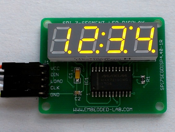
This project is a 7 segment LED display module that can be driven using SPI protocol, so it needs only 3 pins of your mcu to drive 4 x LED displays. It’s based on MAX7219 LED display driver.
Description
Seven segment LED displays are very popular for displaying numeric information because they are very attractive and readable from a far distance and wider viewing angle.
The downside is they are resource-hungry. For example, it requires 12 I/O pins of a MCU to drive a 4-digit seven segment display using a standard time-division multiplexing technique.
Here I present a serial seven segment LED display module that can be used with any MCU using a 3-wire SPI interface. This particular display has four digits (0.40 size) and two colon segments (to support time display) display.
Schematic
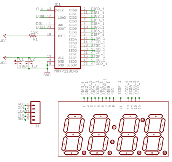
he main controller of this display module is MAXIMs MAX7219 driver chip. Included on-chip are a BCD decoder, multiplex scan circuitry, segment and digit drivers, an 8×8 static RAM to store the digit values, and a 3-pin SPI interface to receive the display data from the host MCU.
The segment current for all LEDs is set through only one external resistor. However, the device also provides a digital control of the display brightness (16 steps from minimum to maximum) through an internal pulse-width modulator.
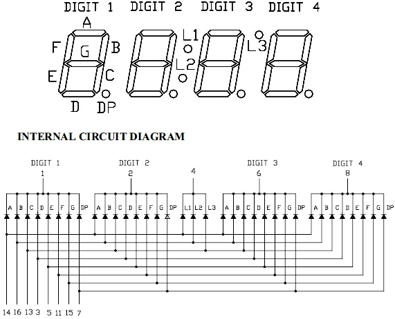
The seven segment module used in this project is LITE-ON, Inc.s LTC-4727JS module, which has LED segment arrangement and pin configuration as shown in figure below.
The interface between MAX7219 and the LTC-4727JS LED module is shown below. The common cathode terminals (Digit 1, Digit 2, Digit 3, and Digit 4) of LTC-4727JS are connected to D3, D2, D1, and D0 pins of MAX7219 driver chip, respectively. The common cathode pin (4) of L1, L2, and L3 LED segments goes to D4 pin of MAX7219. So, in order to turn on L1, L2, and L3 segments, D4 digit select pin of MAX7219 should be active. The display is powered with 5V applied to its VCC pin. Resistor R1 defines the constant current through the LED segments.
Parts List
Interface Example
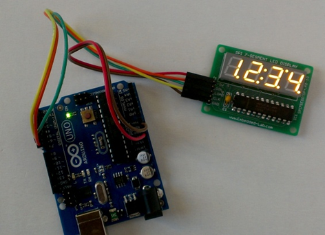
This display module can be easily interfaced with Arduino using the LedControl library. Heres an example that displays numbers 1 through 4 and activates the L1, L2, and L3 segments. The SPI interface pins DIN, CLK, and LOAD of MAX7219 are driven by Arduino digital I/O pins 7, 6, and 5 respectively in this example. However, the LedControl library allows customization of these pins.
Photos
References
- MAX7219 datasheet: http://datasheets.maximintegrated.com/en/ds/MAX7219-MAX7221.pdf
- Arduino LedControl library: http://playground.arduino.cc/Main/LedControl
- PIC12F683 and MAX7219 interface.: http://embedded-lab.com/blog/?p=4935
- Buy 4-digit MAX7219 based displays: https://www.tindie.com/products/rajbex/spi-4-digit-seven-segment-led-display/
- Buy 8-digit MAX7219 based displays: https://www.tindie.com/products/rajbex/spi7segdisp856-kit-eight-digit-serial-spi-seven-segment-led-display-red/







This is what i need! Can i get one of the PCB’s ?
Ordering at PCB Pool would be way too expensive!
Greetings
Andreas
Unfortunately, we don’t have PCBs of this project on hand. I would suggest to contact Raj Bhatt at http://www.embedded-lab.com