
USB to Serial converter using PL2303SA
- Alex Sidorenko
- obddiagn@obddiag.net
- 12.406 Views
- easy
- Non tested
- 0 Likes

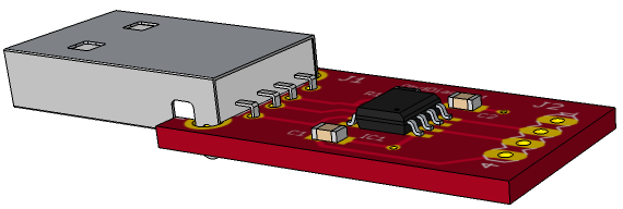
This USB to serial (TTL) converter project is easy to build, it is simple and inexpensive. It is based on the PL2303SA USB to USART bridge from Prolific.
Description
The PL2303SA chip is not required an external crystal as the internal clock oscillator is continuously tuning up to USB bus frequency. Having chip in SO-8 packaging does not require special soldering skills to assemble the project. Please note: the TX and RX signal levels are 3.3 Volts.
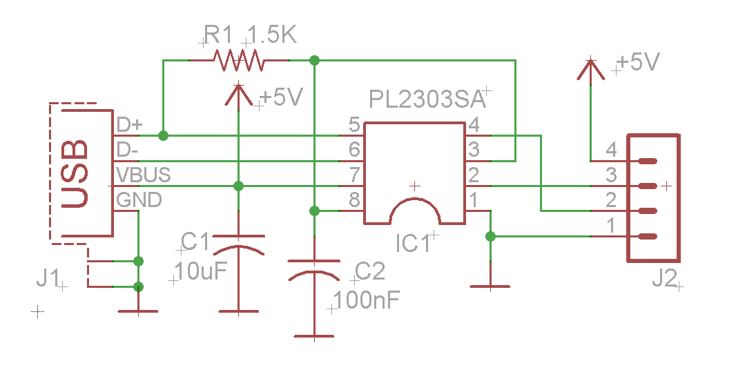
Schematic
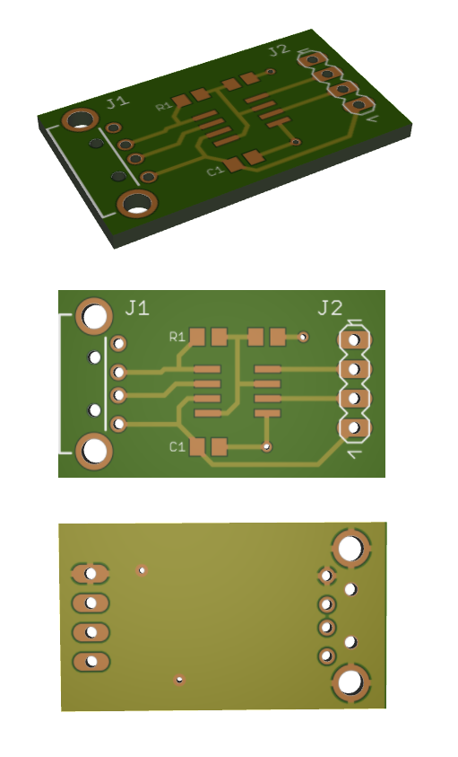
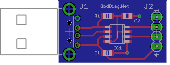
PCB
Please follow and like us:
PCB


Subscribe
Login
0 Comments


