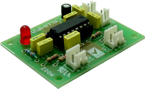
 |
 |
DC Motor Reversing Circuit
source:
Andy Collinson
Description:
A DC motor reversing circuit using non latching push button switches.
Relays control forward, stop and reverse action, and the motor cannot be
switched from forward to reverse unless the stop switch is pressed
first.
Notes:
At first glance this may look over-complicated, but this is simply
because three non-latching push button switches are used. When the
forward button is pressed and released the motor will run continuously
in one direction. The Stop button must be used before pressing the
reverse button. The reverse button will cause the motor to run
continuously in the opposite direction, or until the stop button is
used. Putting a motor straight into reverse would be quite dangerous,
because when running a motor develops a back emf voltage which would add
to current flow in the opposite direction and probably cause arcing of
the relay contacts. This circuit has a built-in safeguard against that
condition.
Circuit Operation:
Assume that the motor is not running and that all relays are
unenergized. When the forward button is pressed, a positive battery is
applied via the NC contacts of B1 to the coil of relay RA/2. This will
operate as the return path is via the NC contacts of D1. Relay RA/2 will
operate. Contacts A1 maintain power to the relay even though the forward
button is released. Contacts A2 apply power to the motor which will now
run continuously in one direction. If now the reverse button is pressed,
nothing happens because the positive supply for the switch is fed via
the NC contact A1, which is now open because Relay RA/2 is energized. To
Stop the motor the Stop switch is pressed, Relay D operates and its
contact D1 breaks the power to relays A and B, (only Relay A is operated
at the moment). If the reverse switch is now pressed and released. Relay
B operates via NC contact A1 and NC contact D1. Contact B1 closes and
maintains power so that the relay is now latched, even when the reverse
switch is opened. Relay RC/2 will also be energized and latched. Contact
B2 applies power to the motor but as contacts C1 and C2 have changed
position, the motor will now run continuously in the opposite direction.
Pressing the forward button has no effect as power to this switch is
broken via the now open NC contact B1. If the stop button is now
pressed. Relay D energizes, its contact D1 breaks power to relay B,
which in turn breaks power to relay C via the NO contact of B1 and of
course the motor will stop. All very easy. The capacitor across relay D
is there to make sure that relay D will operate at least longer than the
time relays A,B and C take to release.
|
 |