

A Very Simple Power Failure Light
- Garrett Fogerlie
- elite_installs@hotmail.com
- 30.374 Views
- moderate
- Non tested
- 0 Likes


Introduction
This is a very basic power failure lighting circuit based around a relay.
This simple circuit has many uses, from lighting up rooms and walkways in the case of a power failure, to monitoring and security uses.
There are many different power failure circuits out there based on 555 timers or transistors but they all have different problems including limited input voltage, price and complexity, and poor backup power. This unit has been designed to work with mains power all the way down to 5 volts, and power 3 LEDs to provide light for a hallway or a child’s room in the event of power failure. The PCB includes many simple add-ons and modifications too.
Specs
- Input Voltage Max: 240 Volts AC
- Input Voltage Min: 5 Volts DC
- Approximant Power Consumption: 450 mW
Schematic
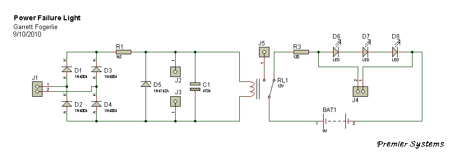
Explanation
This circuit is connected to ac power through J1 then rectified to dc through D1–D4. D5 is a 12 volt zener diode being used along with the resistor R1and the coil resistance of relay RL1 to regulate the input voltage to 12 volts and C1 is used to help smooth this power.
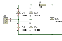
Alternatively a dc voltage of 5 volts or more can be connected directly to J2 and J3, positive to J2 and negative to J3; in this setup the circuit would not need J1, D1–D5, and R1.
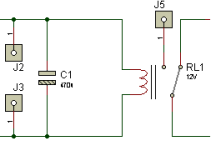
The relay RL1 is a SPDT 5vDc relay and when power is applied to it, it opens the circuit with the LEDs so they are off as long as power is on if the power goes off, the relay closes the circuit and the battery BAT1 powers the LEDs D6, D7, and D8. In this circuit BAT1 is a 9 volt battery that powers the 3 LEDs through R3; however BAT1 can be many different batteries depending on your needs. J4 is also available in parallel with the LEDs to connect a buzzer or etc.
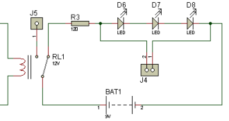
You can also put a switch on one of the wires for BAT1 so you can turn it off so that you don’t drain it when the circuit is not being used.
Parts
| 1 | R1 | 1.2k Ohm |
| 1 | R3 | 120 Ohm |
| 1 | C1 | 470uF |
| 4 | D1-D4 | 1N4004 |
| 1 | D5 | 1N4742A |
| 3 | D6-D8 | White LED |
| 1 | RL1* | 12 Volt SPDT Relay |
| 1 | BAT1 | 9V |
| 1 | – | 9V Battery Connector |
*There are many different relays that can be used, some that even use next to no power.
Please follow and like us:
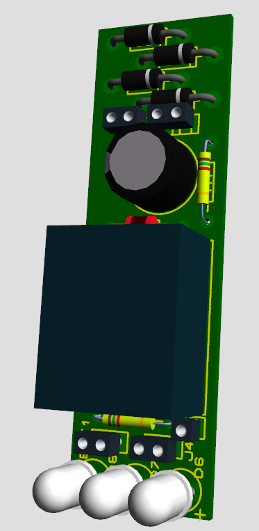
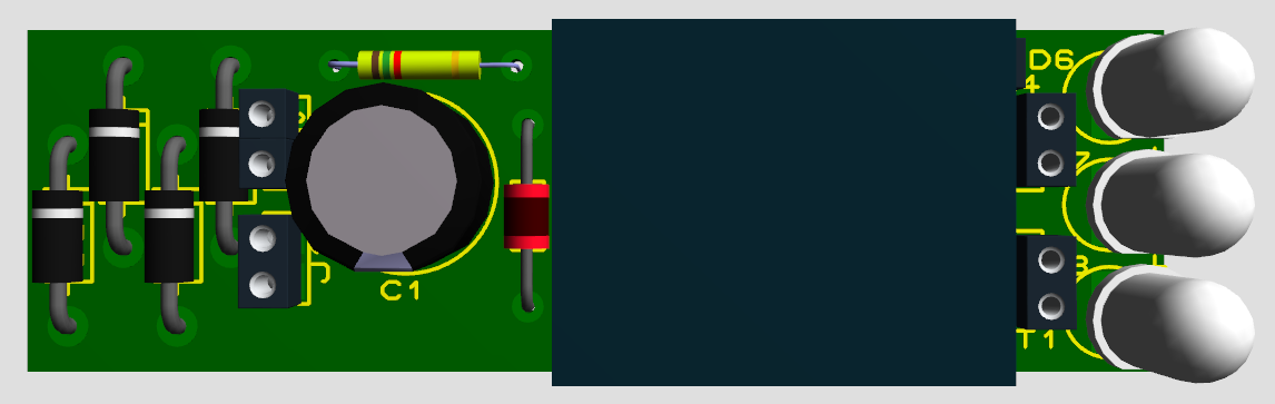
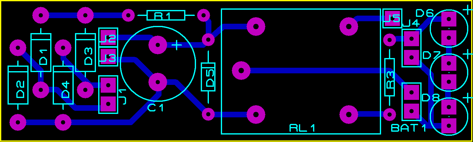
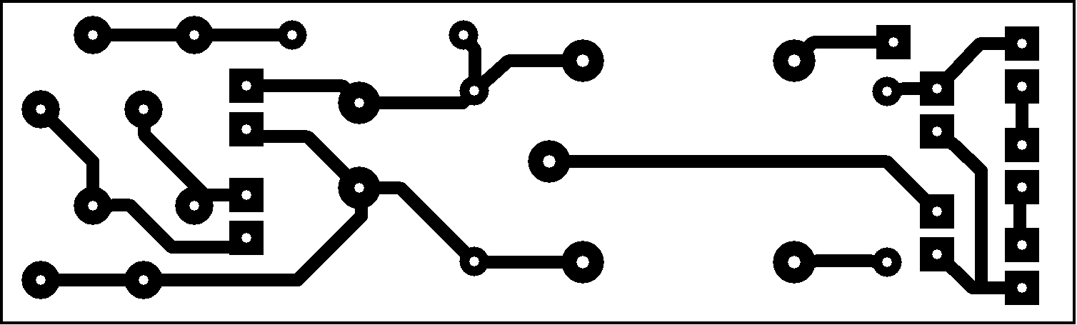
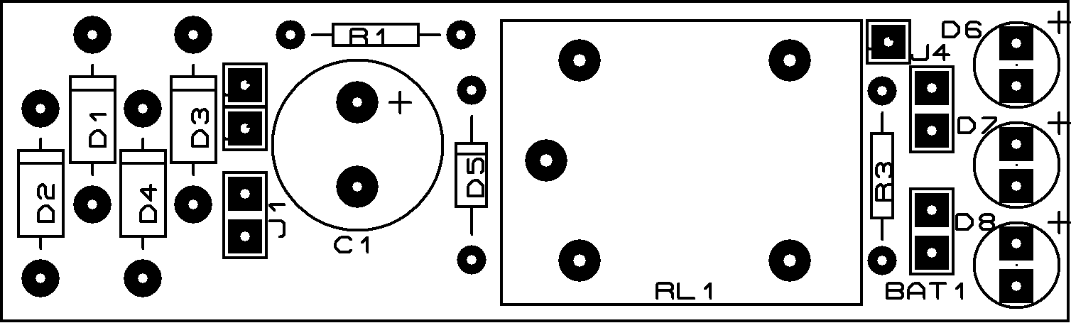
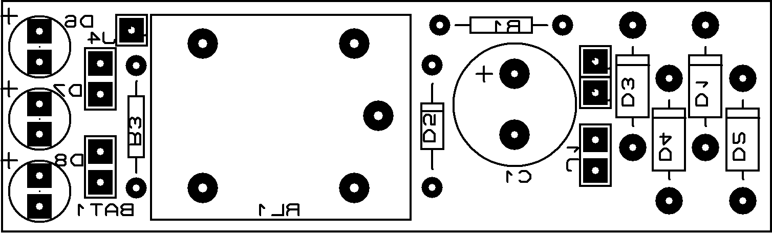
PCB


")
l want simple power failure èlectronic circuit and principle of project
I am interested in electronic projects
the relay is 5v and zener diode use 12v ..why is that ?
There was a typo on the parts list. Thanks for letting me know.
I made a very simple version of this project today. Basically, I wanted a relay activated led strip, so your model was very inspiring. Basically, I took a 12v wall charger, which charges my relay. When the wall power goes off (since I’m having problems with our shower, which is frequently shorting the whole house during bath time), the relay goes back to normally closed (ND) and activates a 9v battery, that is connected to a resistor, connected to a few diodes. Works like a charm!
NC (relay) __ – 9v battery + __ 220 resistor __ + Diodes – __ CM (relay)
Coil (relay)__ 12v wall charger
Simplest ever…. 5V wall charger (such as for a cell phone) to a 3.7V battery (18550) to two LEDs. It’s on all of the time, even during a power failure. LED lasts forever, so why not? Add switches, relays, and photocells if you like. Photocell means it will only operate in the dark, saving battery during outage. I like simple.