
Unipolar 4-Phase Stepper Motor Controller
- Rajkumar Sharma
- 27.508 Views
- moderate
- Tested
- SKU: EL39244
- Quote Now
- 0 Likes

This project is a 4-phase unipolar stepper motor controller.
Description
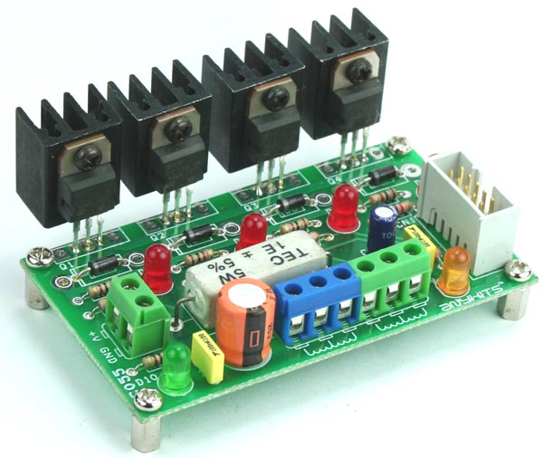
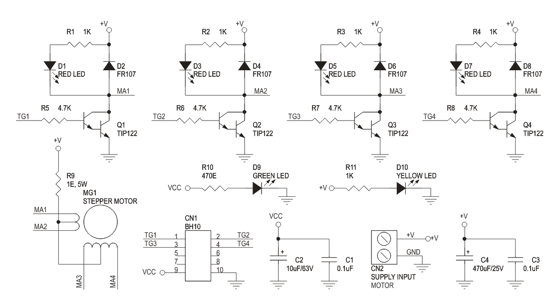
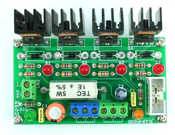
Unipolar 4-Phase Stepper Motor Controller Board will help you control a Stepper Motor or 4 individual Solenoids. This circuit consisting of transistors that serve as current amplifier and also diode to prevent damaging back EMF, circuit uses Darlington transistors to provide high current capacity to unipolar stepper motor. Just provide sequence of pulse using Micro-Controller or descript circuit to roll out the unipolar motor. On board High Watt resistor to control the current, value of the resistor can be set as per your load current requirement.
Specifications
- Box Header (IDC) connector provides for easy interfacing option
- Separate LED indicator for individual Phase
- Screw terminal connector for easy connection of output load and power supply input
- Power-On LED indicator
- Four mounting holes of 3.2 mm each
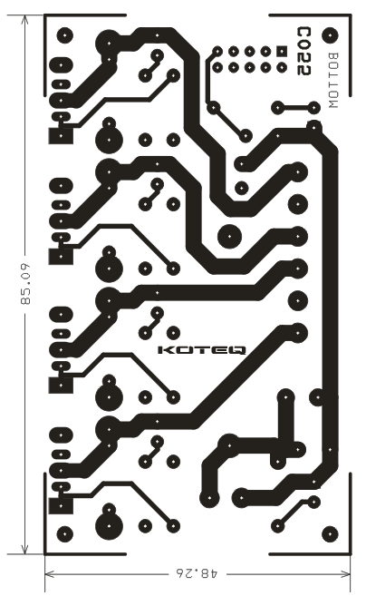
- PCB dimensions 86 mm x 49 mm
Schematic
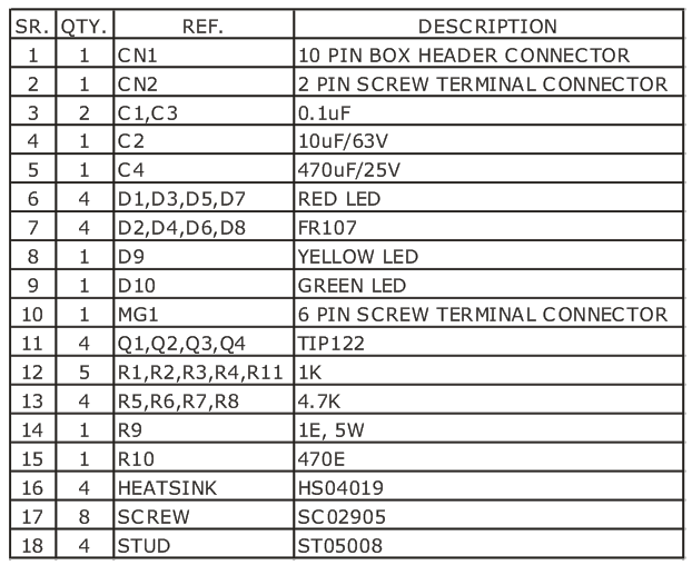
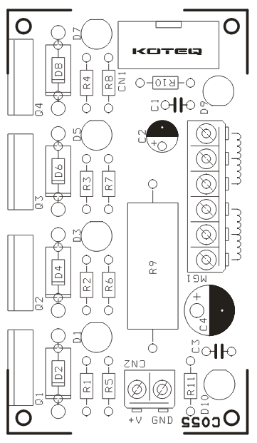
Parts List
Gerber View
Photo
TIP122 Datasheet
Please follow and like us:
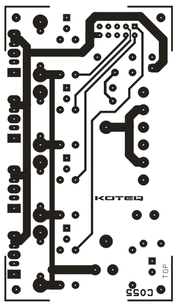
PCB


Thanks for sharing this project.Very elegant and simple,this is what I was looking for! My only question is how big load I can connect ( which type of stepper motor max)?
TIP122 has 5A collector current. That means you can control a motor up to 5A per phase.
many many many thanks
many thanks pro, please how can i connect unipolar stepper model KH56KM2R008 DC 2.31V 3.0 A AND 24V CENTER TAP COIL WITH THIS DRIVER .