

Pulse generator
- Rajkumar Sharma
- 30.413 Views
- easy
- Tested
- SKU: EL34882
- Quote Now
- 1 Likes

Description
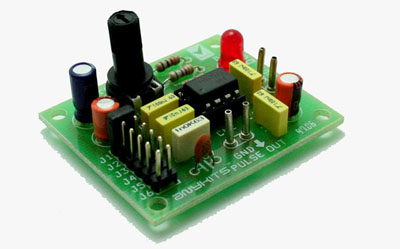
Pulse Generator project will generate a frequency in up to 180 KHz which can form a good test gear project. This project is based on the classic 555 timer IC.
Specifications
- Input : 5-12 VDC Max @ 40 mA
- Provides Square Waves
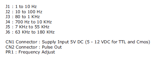
- Range : Jumper selectable and preset tunable range of 1 Hz to 180 KHz
- Power-On LED indicator
- Berg connector for easy connection
- Four mounting holes of 3.2 mm each
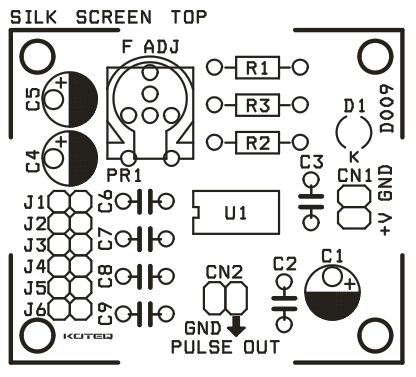
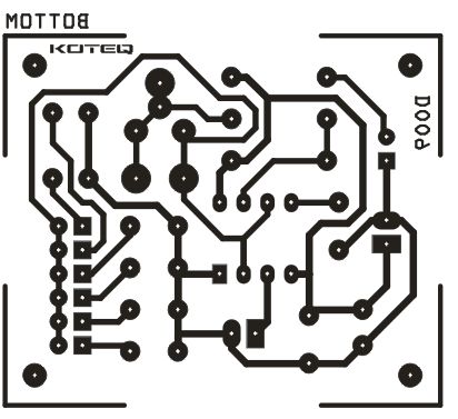
- PCB dimensions 47 mm x 40 mm
Jumpers
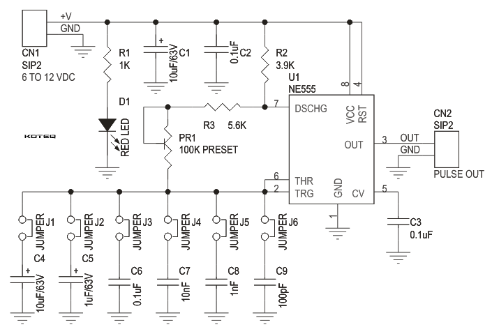
Schematic
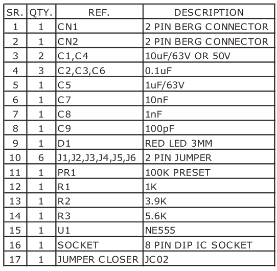
Parts
Please follow and like us:
PCB


Subscribe
Login
0 Comments


