

3-30 V/2.5 A Stabilized power supply
- http://www.smartkit.gr
- 54.935 Views
- moderate
- Tested
- 0 Likes

Copyright of this circuit belongs to smart kit electronics. On this page, we will use this circuit to discuss improvements and we will introduce some changes based on the original schematic.
General Description
This is a very useful project for anyone working in electronics. It is a versatile power supply that will solve most of the supply problems arising in the everyday work of any electronics workshop. It covers a wide range of voltages being continuously variable from 30 V down to 3 V. The output current is 2.5 A maximum, more than enough for most applications. The circuit is completely stabilized even at the extremes of its output range and is fully protected against short-circuits and overloading.
Technical Specifications – Characteristics:
- Input voltage: 24V AC / 3A
- Output current: 2.5 A
- Output voltage: 3-30V DC
How it Works
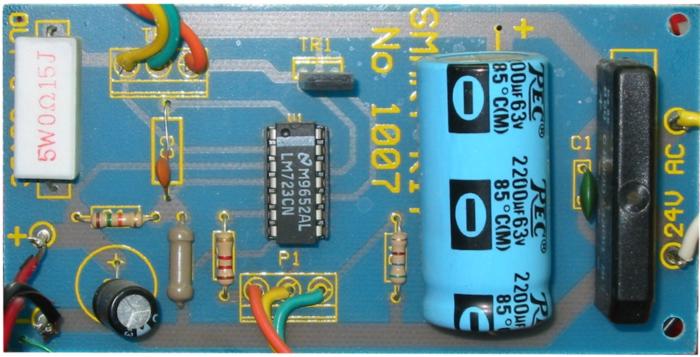
The power supply is using a well known and quite popular VOLTAGE STABILIZER IC the LM 723. The IC can be adjusted for out put voltages that vary continuously between 2 and 37 VDC and has a current rating of 150 mA which is of course too low for any serious use. In order to increase the current handling capacity of the circuit the output of the IC is used to drive a darlington pair formed by two power transistors the BD 135 and the 2N 3055. The use of the transistors to increase the maximum current output limits the range of output voltages somewhat and this is why the circuit has been designed to operate from 3 to 30 VDC. The resistor R5 that you see connected in series with the output of the supply is used for the protection of the circuit from overloading. If an excessively large current flows through R5, the voltage across it increases and any voltage greater than 0.3 V across it has as a result to cut the supply off, thus effectively protecting it from overloads. This protection feature is built in the LM 723 and the voltage drop across R5 is sensed by the IC itself between pins 2 and 3. At the same time the IC is continuously comparing the output voltage to its internal reference and if the difference exceeds the designers standards it corrects it automatically. This ensures great stability under different loads. The potentiometer P1 is used to adjust the out put voltage at the desired level. If the full range from 3 to 30 V is desired then you should use a mains transformer with a secondary winding having a rating of at least 24 V/3 A. If the maxi mum voltage output is not desired you can of course use a transformer with a lower secondary voltage output. (However, once rectified the voltage across the capacitor C2 should exceed by 4-5 volts the maximum output expected from the circuit.
Construction
First of all let us consider a few basics in building electronic circuits on a printed circuit board. The board is made of a thin insulating material clad with a thin layer of conductive copper that is shaped in such a way as to form the necessary conductors between the various components of the circuit. The use of a properly designed printed circuit board is very desirable as it speeds construction up considerably and reduces the possibility of making errors. Smart Kit boards also come pre-drilled and with the outline of the components and their identification printed on the component side to make construction easier. To protect the board during storage from oxidation and assure it gets to you in perfect condition the copper is tinned during manufacturing and covered with a special varnish that protects it from getting oxidised and makes soldering easier. Soldering the components to the board is the only way to build your circuit and from the way you do it depends greatly your success or failure. This work is not very difficult and if you stick to a few rules you should have no problems. The soldering iron that you use must be light and its power should not exceed the 25 Watts. The tip should be fine and must be kept clean at all times. For this purpose come very handy specially made sponges that are kept wet and from time to time you can wipe the hot tip on them to remove all the residues that tend to accumulate on it.
DO NOT file or sandpaper a dirty or worn out tip. If the tip can not be cleaned, replace it. There are many different types of solder in the market and you should choose a good quality one that contains the necessary flux in its core, to assure a perfect joint every time.
DO NOT use soldering flux apart from that which is already included in your solder. Too much flux can cause many problems
and is one of the main causes of circuit malfunction. If nevertheless you have to use extra flux, as it is the case when you have to tin copper wires, clean it very thoroughly after you finish your work. In order to solder a component correctly you should do the following:
Clean the component leads with a small piece of emery paper.
Bend them at the correct distance from the component body and insert the component in its place on the board. You may find sometimes a component with heavier gauge leads than usual, that are too thick to enter in the holes of the p.c. board. In this case use a mini drill to increase the diameter of the holes slightly. Do not make the holes too large as this is going to make soldering difficult afterwards. Take the hot iron and place its tip on the component lead while holding the end of the solder wire at the point where the lead emerges from the board. The iron tip must touch the lead slightly above the p.c. board. When the solder starts to melt and flow wait till it covers evenly he area around the hole and the flux boils and gets out from underneath the solder. The whole operation should not take more than 5 seconds. Remove the iron and allow the solder to cool naturally without blowing on it or moving the component. If everything was done properly the surface of the joint must have a bright metallic finish and its edges should be smoothly ended on the component lead and the board track. If the solder looks dull, cracked, or has the shape of a blob then you have made a dry joint and you should remove the solder (with a pump, or a solder wick) and redo it. Take care not to overheat the tracks as it is very easy to lift them from the board and break them. When you are soldering a sensitive component it is good practice to hold the lead from the component side of the board with a pair of long-nose pliers to divert any heat that could possibly damage the component. Make sure that you do not use more solder than it is necessary as you are running the risk of short-circuiting adjacent tracks on the board, especially if they are very close together. After you have finished your work cut off the excess of the component leads and clean the board thoroughly with a suit able solvent to remove all the flux residues that may still remain on it.
Start building the circuit by placing the pins on the board and soldering them. You must be very careful when soldering the components that are going to carry heavy currents as your joints must be capable of withstanding the maximum current without getting hot. Solder the IC socket in its place taking care not to insert it the wrong way round and then put the resistors in their places on the board. Resistor R5 should be soldered in such a way as to keep its body slightly separated from the p.c. board to let the air circulate around the component and cool it. Continue your work with the capacitors. Be careful not to insert the electrolytic the wrong way round. The polarity is marked on the capacitors and the p.c. board is also marked accordingly. Insert the rectifier bridge in its place. The bridge is a heavy duty type and has leads made of heavier gauge wire than usual. If you have any difficulty inserting them in the p.c. board you can enlarge the holes with a mini drill. (Automatic production of p.c. boards requires all the holes on the board to be of the same diameter).
Do not however make the holes too wide as you are going to find soldering the leads much more difficult afterwards. Solder TR1 in its place and mount TR2 on the heatsink following the diagram and making sure there is no electrical connection between the heat sink and the transistor. Dont forget the insulators, and use heat transfer compound between the transistor body and the heat sink. Using heavy gauge wires connect TR2 to the board and finally using a flat ribbon cable connect the potentiometer with the rest of the circuit. Insert the VOLTAGE REGULATOR in its socket and your power supply is ready. Now make a final inspection of your work to ensure that there are no mistakes that could cause a lot of trouble later. If everything looks OK you can connect the input of the circuit (it is marked «24 VAC» on the board) to the secondary winding of the transformer. Connect a voltmeter to the pins marked «OUT 3-30 V» and using a mains lead connect the primary of the transformer to a convenient power out let. If everything was done properly the voltmeter should give a reading and turning the potentiometer should make it change.
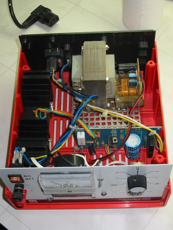
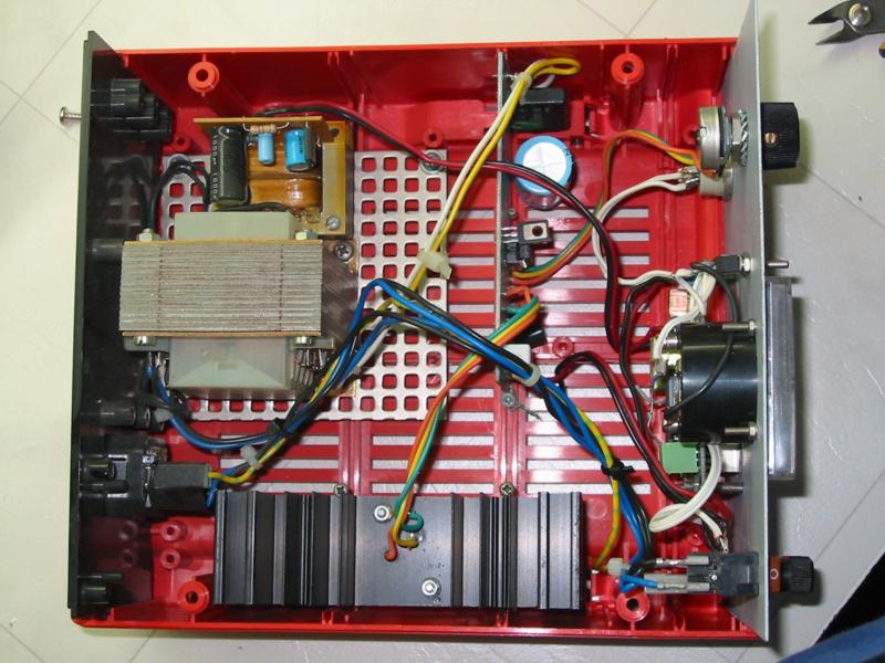
Slight variations from the minimum and maximum voltages specified are normal, are caused from component tolerances and should not worry you. Although the circuit works with low voltages and is quite safe to touch any part while it is in operation it needs a mains transformer to supply this low voltage and the primary of the transformer is connected to the mains which makes it very dangerous. The best idea is to use a case for everything in order to make a complete stand alone power supply for your experiments. Smart Kit also makes a suitable case for this supply with a printed front panel, ready drilled for the output connectors, switches, fuse holder and panel instruments.
Parts List
| R1 = 560R 1/4W | C1 = 100nF |
| R2 = 1,2 K 1/4W | C2 = 2200uF 35-40V |
| R3 = 3,9 K 1/4W | C3 = 100 pF |
| R4 = 15K 1/4W | C4 = 100uF/ 35V |
| R5 = 0,15R 5W | |
| D = B40 C3300/2200, 3A rectifier bridge | |
| P1 = 10K potesiometer | TR1 = BD 135 |
| IC = LM723 | TR2 = 2N3055 |
CAUTION
This circuit works from the mains and there are 220 VAC pre sent in some of its parts. Voltages above 50 V are DANGEROUS and could even be LETHAL. In order to avoid accidents that could be fatal to you or members of your family please observe the following
rules:
- DO NOT work if you are tired or in a hurry, double check every thing before connecting your circuit to the mains and be ready to disconnect it if something looks wrong.
- DO NOT touch any part of the circuit when it is under power.
- DO NOT leave mains leads exposed. All mains leads should be well insulated. -DO NOT change the fuses with others of higher rating or replace them with wire or aluminium foil.
- DO NOT work with wet hands. -If you are wearing a chain, necklace or anything that may be hanging and touch an exposed part of the circuit BE CAREFUL. USE ALWAYS a correct mains lead with the correct plug and earth your circuit correctly. If the case of your project is made of metal make sure it is properly earthen. If it is possible use a mains transformer with a 1:1 ratio to isolate your circuit from the mains. When testing a circuit that works off the mains wear shoes with rubber soles, stand on dry non conductive floor and keep one hand in your pocket or behind your back. If you take all the above precautions you are reducing the risks you are taking to a minimum and this way you are protecting your self and those around you. A carefully built and well insulated device does not constitute any danger for its user. BEWARE: ELECTRICITY CAN KILL IF YOU ARE NOT CAREFUL.
Here are some photos from this power supply finished and installed in a box.
Please follow and like us:
PCB


 Converter")
Please could you tell me in what percent (%) should I print the pcb scheme? I save it and when I try to print it I think that it is
much bigger.,….
Thank you very much,
Alexandros
One trick will be to print it multiples times and try to fit the IC in PCB, this way you will have to print the PCB 2-3 times changing the dimensions.
Thank you very much for your answer my friend!!!
plz tell me what is the current rating of the input from the transformer ?
plz reply quick
and is C2 63 V or 35-40 V ???
WHAT SHOULD BE THE CURRENT INPUT FROM THE TRANSFORMER ????
Can u plz tell me 4 to 5 application of versatile power supply
in the above specification the input is 24v 3amp & 3-39v output. you mean in your last comment is 30v. in voltages of 24v input how many volt can reach?
Sorry for the misunderstanding. The transformer should be 24V/3A. This is Vrms value and transformer can produce 34Vpeak thus the output can reach 30V.
can anyone send the methodology for calculating the elements of this circuit
can you make the range output 1.2v-30v? is it possible?
It is not possible to achieve 1.2V at the output with that circuit. Instead you may take a look at this one https://www.electronics-lab.com/project/0-30-vdc-stabilized-power-supply-with-current-control-0-002-3-a/
Hi .. I mounted the source according to your explanation however my source the voltage variation was between 10 to 25V … all the components are mounted correctly .. you know what can be wrong?
Hi i have a question regarding the bridge rectifier at the beginning of this circuit. Why can we not do away with the transformer and use a large bridge rectifier, if the output from rectifier is in the 600v area then why can’t we have a 0-600vdc output supply (only in theory) and at whatever current could be produced say if output was to be set at 12vdc?
or
if 600vdc from Rect. was dropped to 12v what max theoretical current could be delivered? at say with same load on output of 1000 ohms and how wold the circuit look to protect against a 10 ohms load on it?