

Digital Multiple Voltage Power Supply
- Garrett Fogerlie
- elite_installs@hotmail.com
- 38.401 Views
- medium
- Non tested
- 0 Likes

1.2 to 33 Volts DC @ 3 Amps
Description
This is simple to build microcontroller controlled power supply that can switch between 5 (or 32 or more) preconfigured voltages between 1.2 to 33 volts dc and up to 3 amps. This guide will walk you through every aspect of the building process; however some basic familiarity with electronics and microcontrollers will be required to program the microcontroller.
Specifications
- Input Voltage: 33 Volts DC* Max
- Input Current: 3 Amps Max
- Output Voltage: 5 Preset Voltages Between 1.2 to 33** Volts DC
- Output Current: 3 Amps Max
*There is no bridge rectifier so the input voltage must be DC.
**Output voltage wont exceed input voltage.

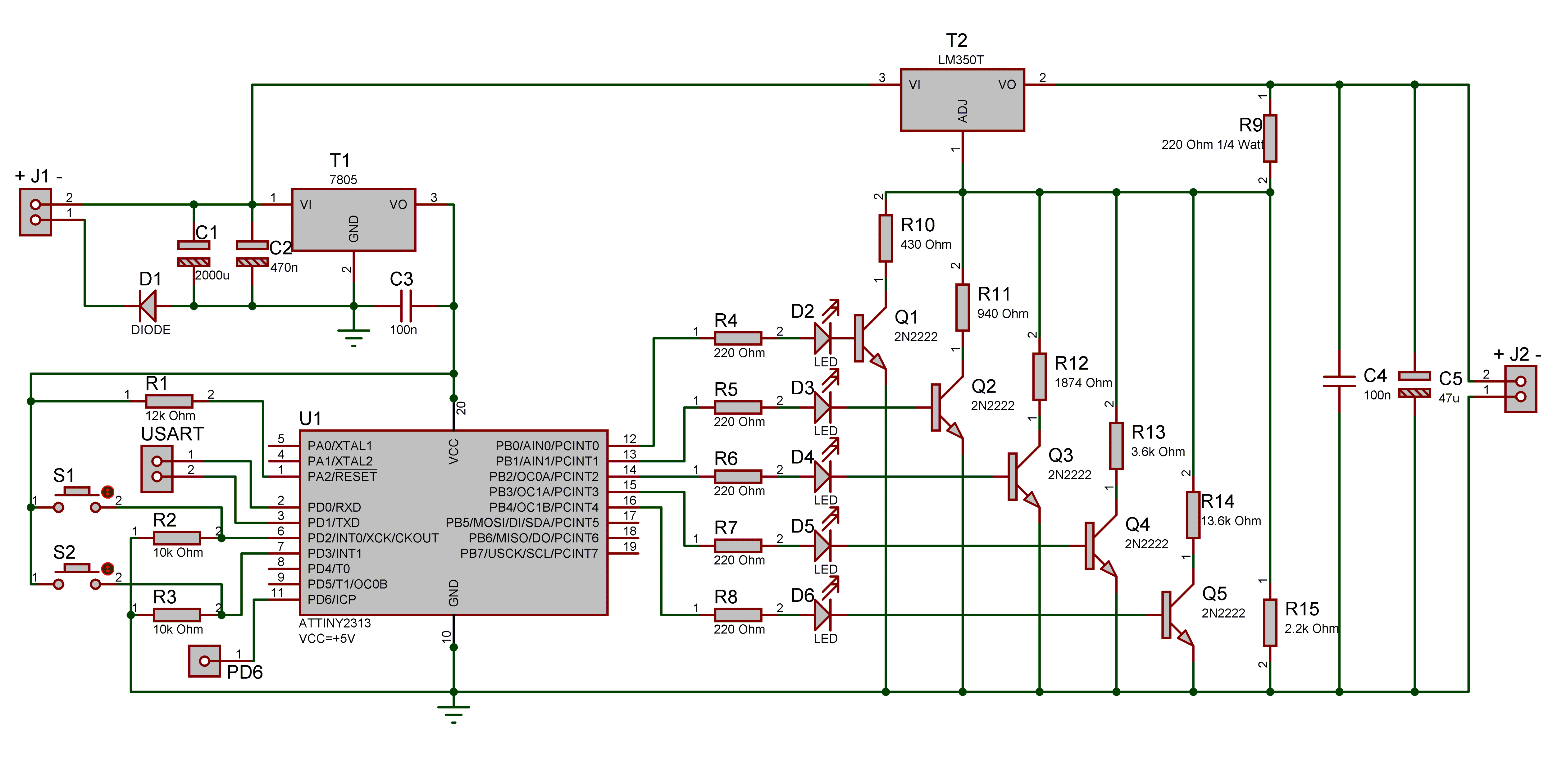
Description
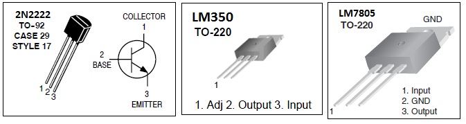
The hart of this circuit is a LM350 adjustable positive voltage regulator (T2). The voltage regulator is capable of supplying in excess of 3 amps over an output voltage range of 1.2Vdc to 33Vdc. Its ease of use, thermal overload protection, large voltage range, current limiting, and high ripple rejection make it a great choice for a variable power supply. The voltage (on the Vout pin) is regulated by the current traveling out the ADJ pin through a resistor to ground. Therefore by changing the resistance the outputted voltage will change.
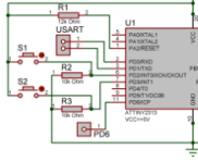
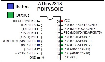
Changing the resistance is controlled by an Atmel ATtiny2313 microcontroller (U1). The microcontroller has 2 main functions collecting user input and changing the output. Collecting user input is easy; there are two buttons (S1-S2), one to go to the next voltage and the other to go to the previous voltage. The buttons are connected to the microcontroller pins PD2 and PD3. When a button is pressed the microcontroller sees a high signal (+5 volts) on the corresponding pin. The rest of the time, when a button is not pressed the microcontroller sees a low signal (0 volts) on the corresponding pin because the pin in connected to ground trough a resistor (R2-R3), called a pull down resistor.
When the microcontroller sees an input pin change from low to high, it sends a high signal (+5 volts) to an output pin. There are five output pins PB0 PB1 PB2 PB3 PB4, each going through a small current limiting resistor (R4-R8) to a led (D2-D6), so you can see what the current selected voltage is, then to the base pin of a small 2n2222 transistor (Q1-Q5).
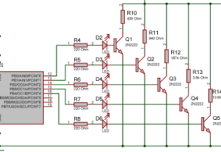
Each transistor has a resistor connected to its collector pin and its emitter pin connected to ground. When the transistor receives voltage on its base pin, power will flow from the collector to the emitter. This basically turns a resistor on or off which changes the current on the ADJ pin of the LM350 (T2).
The LM7805 (T1) is just a basic fixed 5 volt dc regulator to provide power to the microcontroller.
Diode D1 protects the circuit from a positive voltage being attached to ground.
Capacitors C1 C2 C3 C4 and C5 are used to keep steady power and decouple parts of the circuits.
The LEDs dont need to be mounted to the PCB. They can be mounted in a panel to easily display the selected voltage, or excluded completely and replaced with a jumper wire. They are currently set at the following values:
D2 -> 3.3v, D3 -> 5v, D4 -> 7v, D5 -> 9v, D6 -> 12v
Changing the value of R9-R15 will change the preset voltages to any voltage you want.
![]()
Where Ra is the component R9 and Rb is the component R10-R14 in parallel with R15. Remember that R10-R14 is in parallel with R15 and their value needs to be calculated as such.
![]()
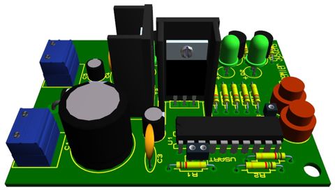
Schematic
Diagramms
Parts List
| Quantity | Reference | Description |
| 1 | R1 | 12k Ohm 1/8 Watt Resistor |
| 2 | R2, R3 | 10k Ohm 1/8 Watt Resistor |
| 5 | R4-R8 | 220 Ohm 1/8 Watt Resistor |
| 1 | R9 | 220 Ohm 1/4 Watt Resistor |
| 1 | R10 | 430 Ohm 1/8 Watt Resistor |
| 1 | R11 | 940 Ohm 1/8 Watt Resistor |
| 1 | R12 | 1874 Ohm 1/8 Watt Resistor |
| 1 | R13 | 3.6k Ohm 1/8 Watt Resistor |
| 1 | R14 | 13.6k Ohm 1/8 Watt Resistor |
| 1 | R15 | 2.2k Ohm 1/8 Watt Resistor |
| 1 | C1 | 2000uF 50v Capacitor |
| 1 | C2 | 470nF 50v Capacitor |
| 2 | C3, C4 | 100nF Capacitor |
| 1 | C5 | 47uF Capacitor |
| 1 | U1 | Atmel ATTINY2313 Microcontroller |
| 5 | Q1-Q5 | 2N2222 NPN Transistor |
| 1 | D1 | 1N5402 3 Amp Diode |
| 5 | D2-D6 | 5mm generic LED |
| 1 | T1 | 7805 voltage regulator 5volt |
| 1 | T2 | LM350T |
| 2 | S1, S2 | Generic Momentary Switch or Button |
| 2 | J1*, J2* | Tyco 282841-2 |
*Not necessary
MCU Programming
The C# code for the microcontroller is in the file: MCU_Power_Supply
It can be easily modified to control 36 different voltages with this same circuit.
Set the SUT_CKSEL fuse to: Int. RC Osc. 4 MHz; Start-up time: 14 CK + 65 ms
Make sure the CKDIV8 fuse is not set.
The PCB also has connections for Rx Tx and PD6 so that an LCD display, computer control, and extra inputs and outputs can easily be added.
Links
- LM350 http://www.fairchildsemi.com/ds/LM%2FLM350.pdf
- 2N2222 http://www.onsemi.com/pub_link/Collateral/P2N2222A-D.PDF
- ATtiny2313 http://www.atmel.com/dyn/resources/prod_documents/2543S.pdf
Please follow and like us:
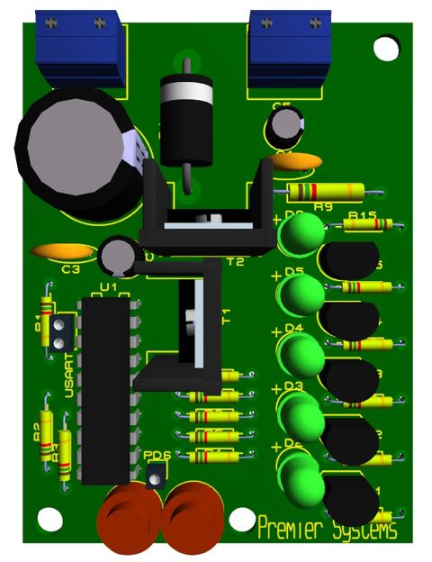
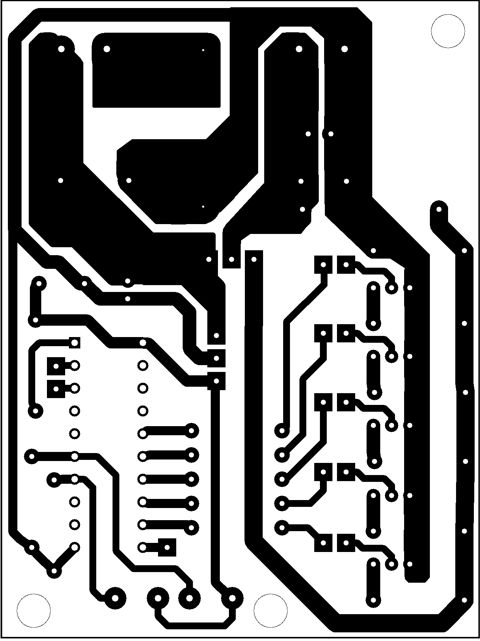
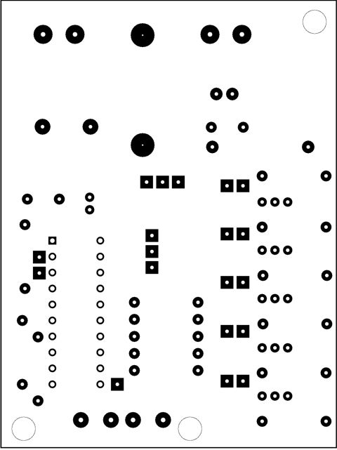
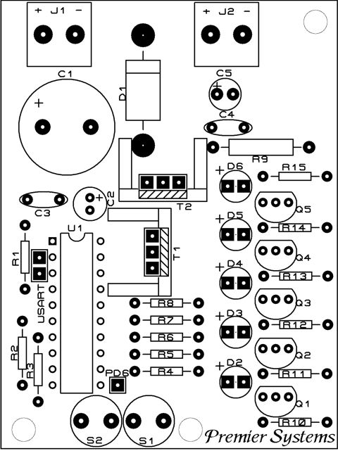
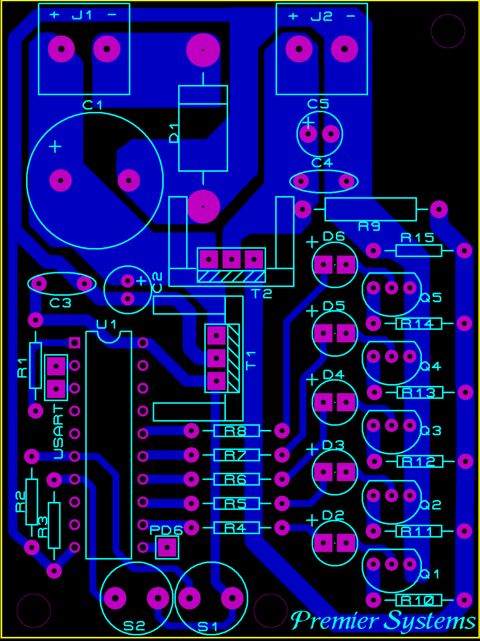
PCB


Pls reup source file.
Source code link is updated. Please check again.
For universel AC 110-230v Ac input to 5-500v output how can modifiy it .Is it posible? if posible what will be the change? .Please respons
Hi,
I’m new to electronics, Just to double check, the power supply should connect to J1 right ? And the output will be from J2
Yes, right!