9V to 48V DC-DC Converter
- Konstantin Dimitrov
- k_dimitrov@abv.bg
- 43.352 Views
- moderate
- Non tested
This project is a 8-12Vdc to +48Vdc DC-DC converter based on MC34063 switching regulator.
Description
It’s a simple project of a DC-DC converter to make a phantom power supply for professional microphones. It can deliver 15-20mA at 48VDC. It ‘s based on MC34063 DC-DC step-up, step-down and boost converter. Input is between 8-12V DC and the output +48VDC/10-20mA.
Schematic
Photos
3D PCB renderings


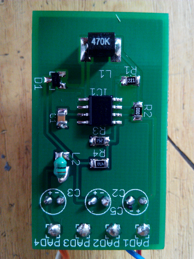
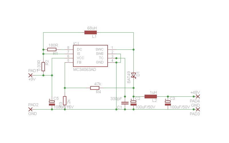
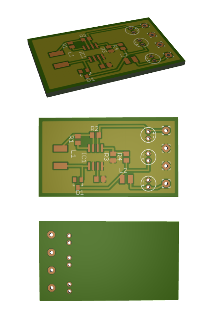
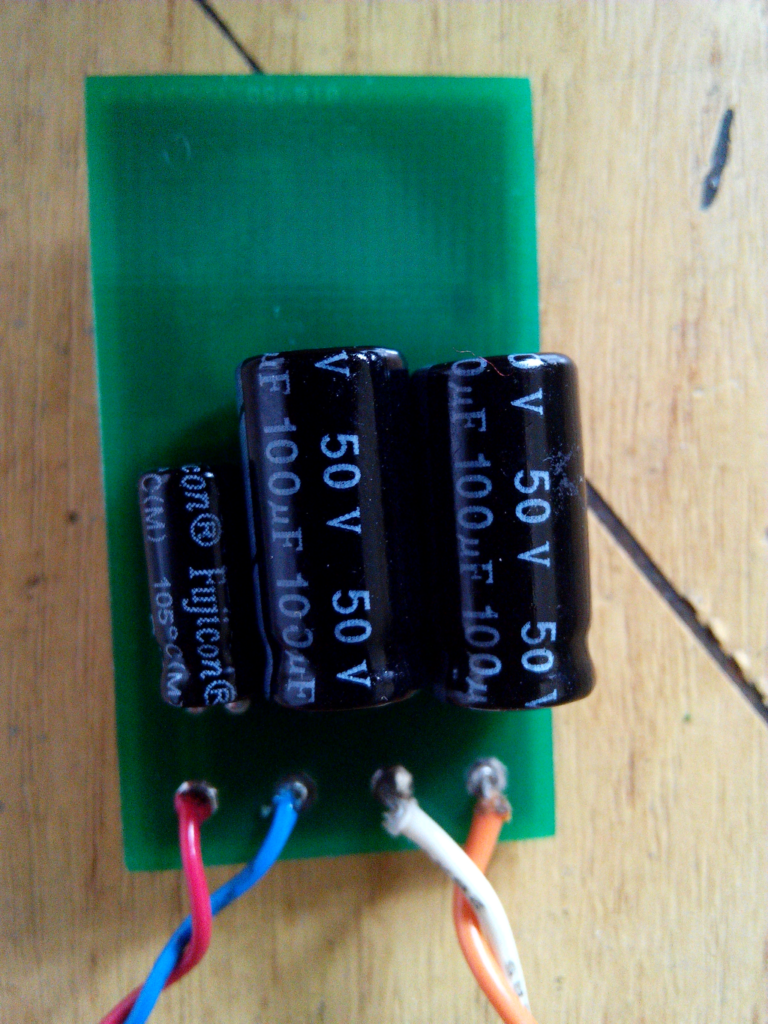
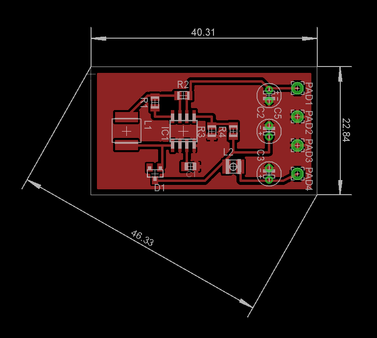
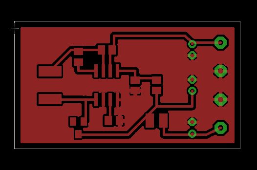
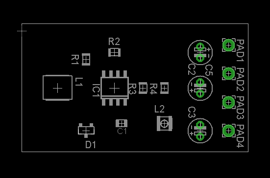


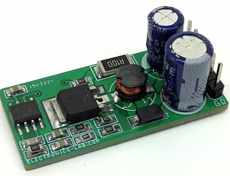
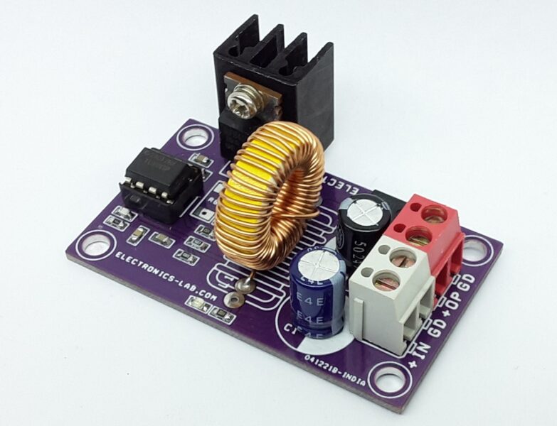
thank you a lott
best regards
Thank you for all people that like my first project
Nice work, but you forgot to save gnd polygon
I need boost converter 12 to 80 dc
By ic.mosfet.coil
I use uc38 not by transformer
Thanks for project.
Can i use BAT43 instead of BAT49 ?
Thanks for your kind words. BAT43 has 200mA continuous forward current and BAT49 has 500mA, so most probably the BAT43 diode will fail.
What is L1 and L2? Is it coil?
Yep, these are two coils.
Is it possible to have a ready base?
Unfortunately we don’t sell kits or assembled products of this.
I chucked this on a bread board, and it provided 15VDC from 9VDC supply. Anybody else build it out?
Scratch that. Works famously when you hook it up correctly!
Thanks
Where is the microphone input and output, I only see power input and output,
could anyone help me with this project?
Which microphone do you refer? What are you looking for?
What inductor did you use? I am getting an overheating issue.
You will need a more powerful inductor for this step-up converter. The author seems to have used a low current inductor. You can try a wire wound one with inductance value close to 70uH
Hello,
I reproduced the schematic and try with +12V and I only have 30 V instead of 48V. Do you have an idea about the problem. Which component define the output voltage value ? Thank you
R3 and R4 resistor divider define the output voltage. Check the datasheet on how to select them.
I think the L1 should be 300uH instead of the 68uH.
My calculations:
**Conditions:**
V_out: 48V
V_in: 8 … 12V
V_f: 0.6V
V_sat: 0.5V
f: 100kHz
I_out: 14.7mA
**Results:**
t_on/t_off: 5.8
t_on+t_off: 10us (f = 100kHz)
t_off: 1.47us
t_on: 8.53us
C_t: 341 pF
L_min 299uH <—- 5 times greater than in the schematic
I_peak_sw: 200 … 314 mA
Rsc: 1.05 ohm
0.22Rsc: 0.23 ohm
Am I right?
Check some calculations here: https://bigdanzblog.wordpress.com/2016/01/15/5v-to-48v-switch-mode-power-supply-using-mc34063/ and a MC34063 calculator here: http://www.nomad.ee/micros/mc34063a/index.shtml It gives Lmin=382 uH , then yes, the schematic is not based on reliable calculations.
Note, that you are above the MC34063A IC absolute maximum ratings… The datasheet says that no pin accepts voltage above 40V !!!
Howto increase the output curent to 2A at 48V ?
Thanks a lot! For a condenser mic, do you know how much time does the battery last?
You have to know the current draw of your load and the battery capacity to calculate this,
Need to make or buy a 9v dc to 40-80v dc unit, small and inexpensive. The one I see here recommended? Or something else? Will only pull power occationally, must take rain and freezing weather. Standing by.
This is the only one we have for these voltages, how many pieces do you need? We can design a new board for you if you can afford the cost.
This board doesnt work properly. The chip only is rated for 40V, you are running it at 48v. asking
for trouble