
FM VCO Transmitter
- Spiliopoulos Kwstas
- spilkos@windtools.gr
- 27.480 Views
- medium
- Tested
- 0 Likes

This is a VCO FM Transmitter with range 500m – 4km depending on antenna used.
Specifications
- Power supply: 12-14 V stab., 100 mA
- RF power: 400 mW
- Impedance: 50-75 ohm
- Frequency range: 87,5-108 MHz
- Modulation: wideband FM
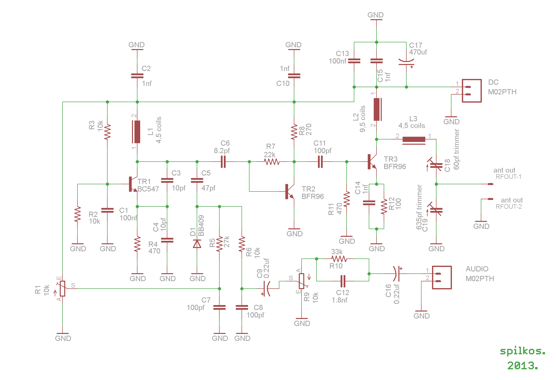
Description
This circuit originally published on www.pira.cz but a new PCB design is introduced here.
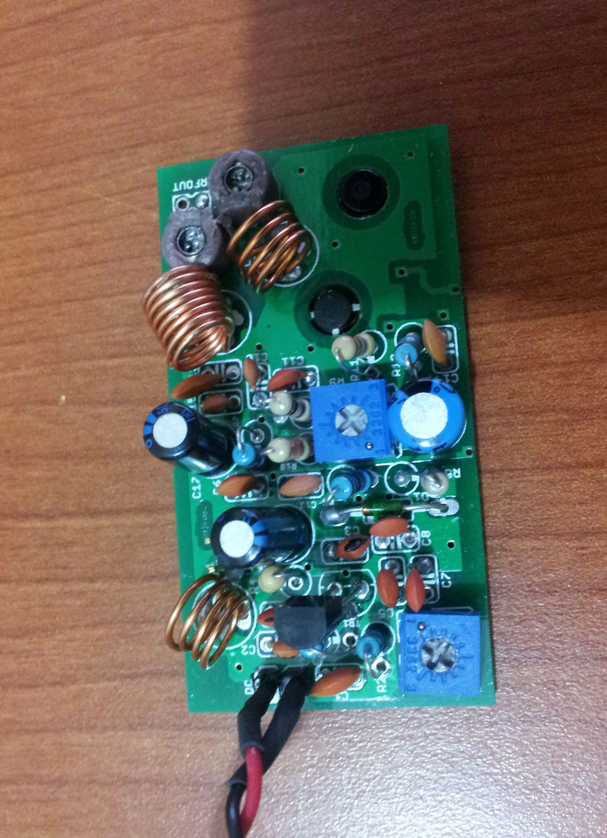
Connect the 6 V / 0,1 A bulb to the output and use R1 to tune the right frequency. Maybe you might stretch coils of the L1. Then use C14 and C15 to adjust the highest power (the highest light of the bulb). Then you can connect antenna and audio signal.
Adjust R2 until the audio sounds as loud as the other stations. With good antenna (dipole placed outdoor and high) the transmitter has very good coverage range about 500 meters, the maximal coverage range is up to 4 km.
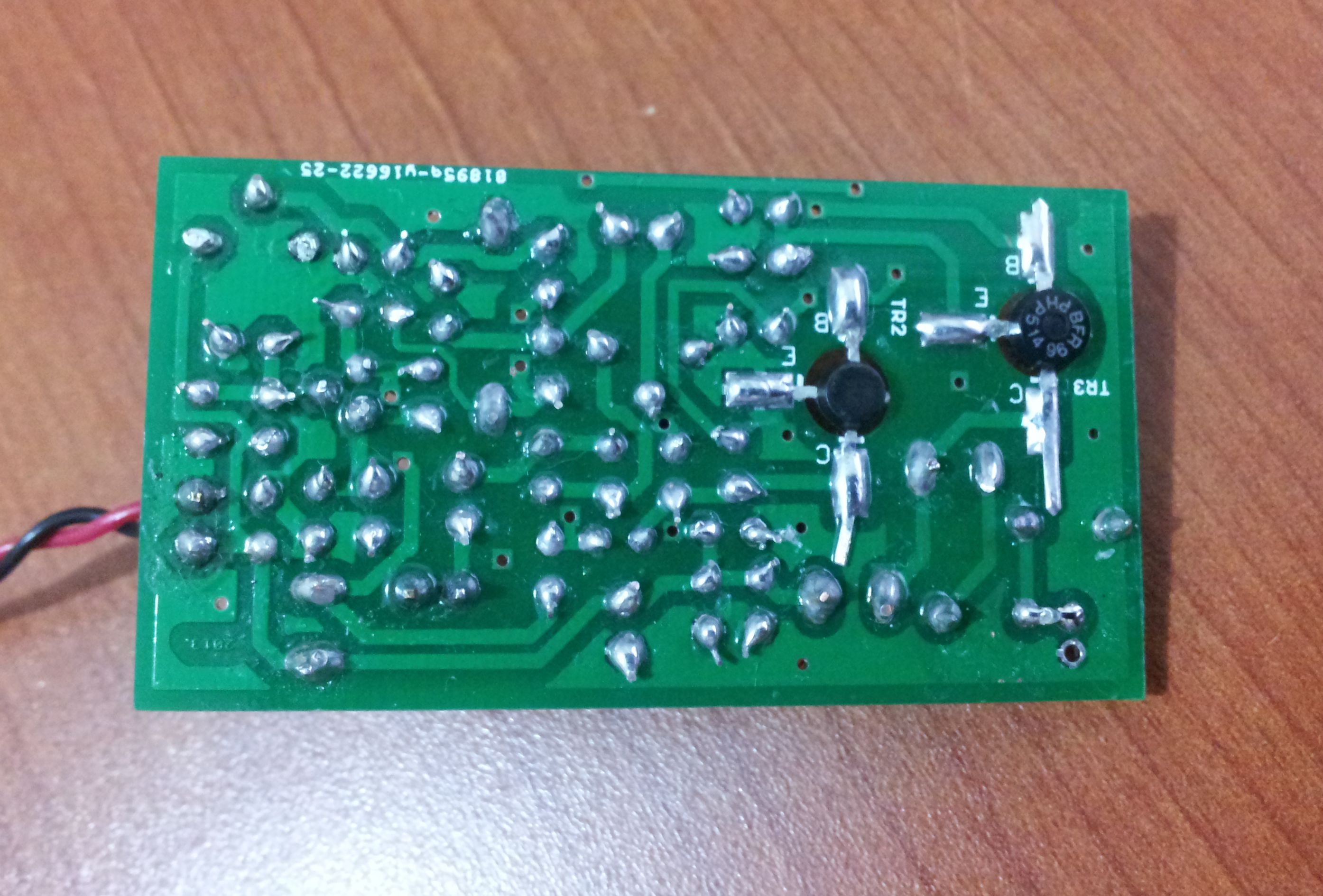
Photos
Please follow and like us:
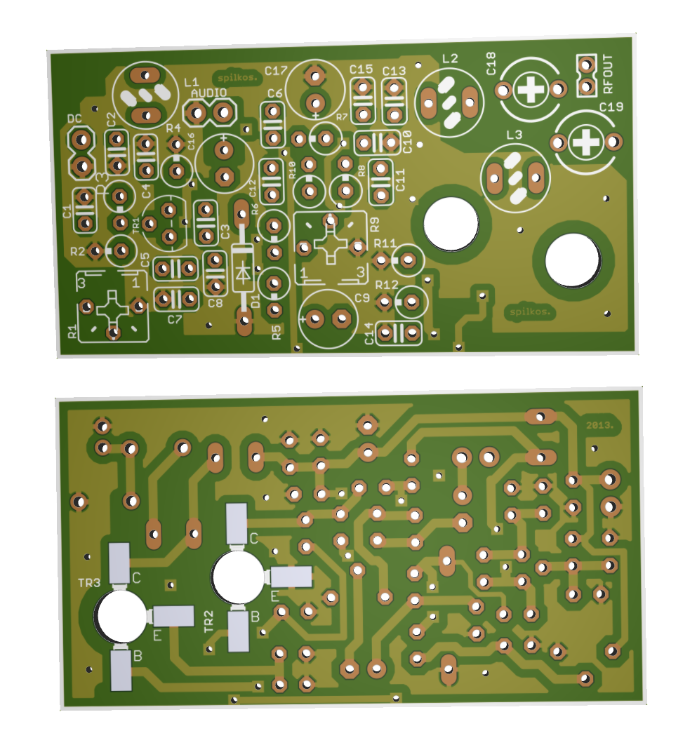
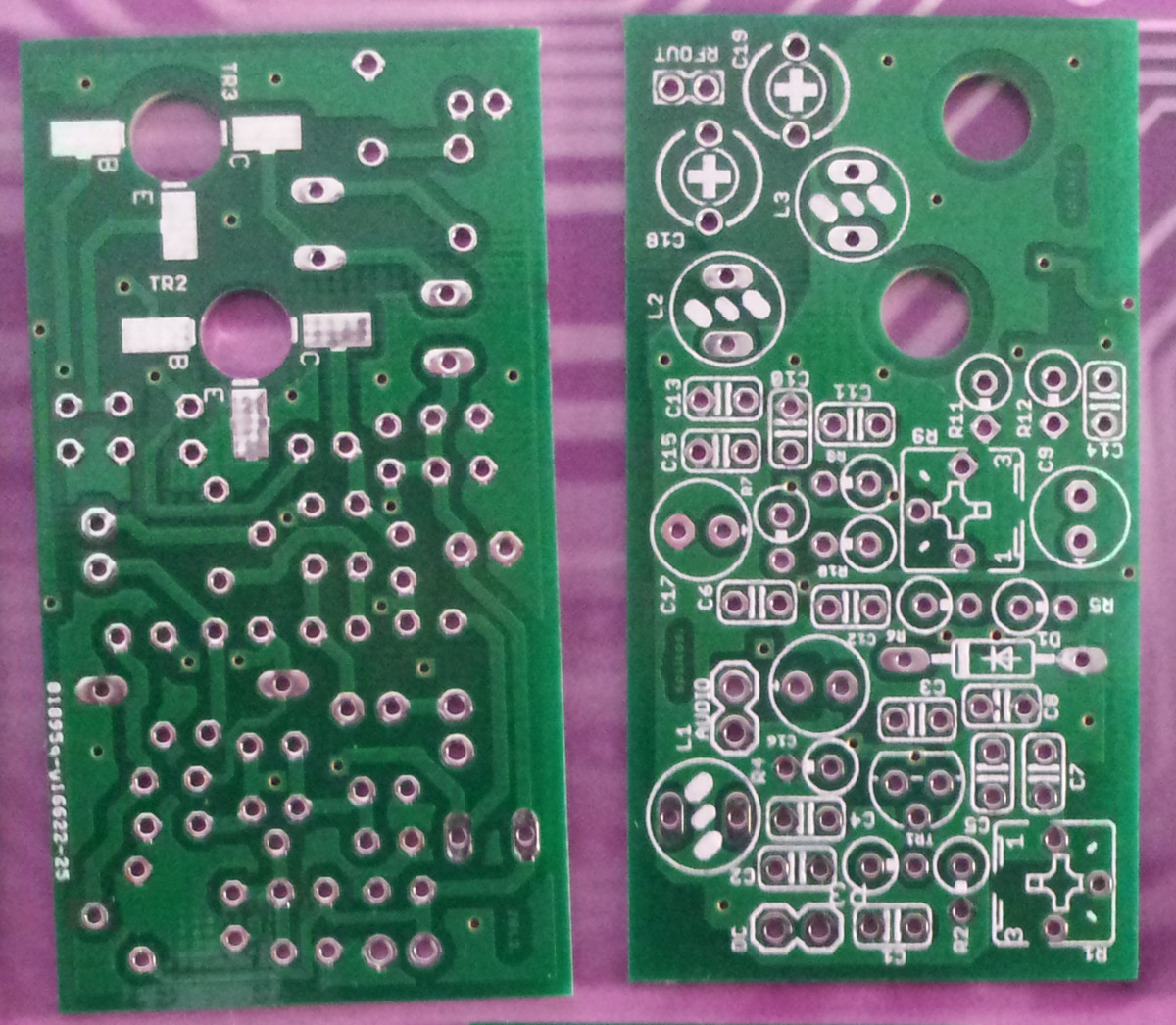
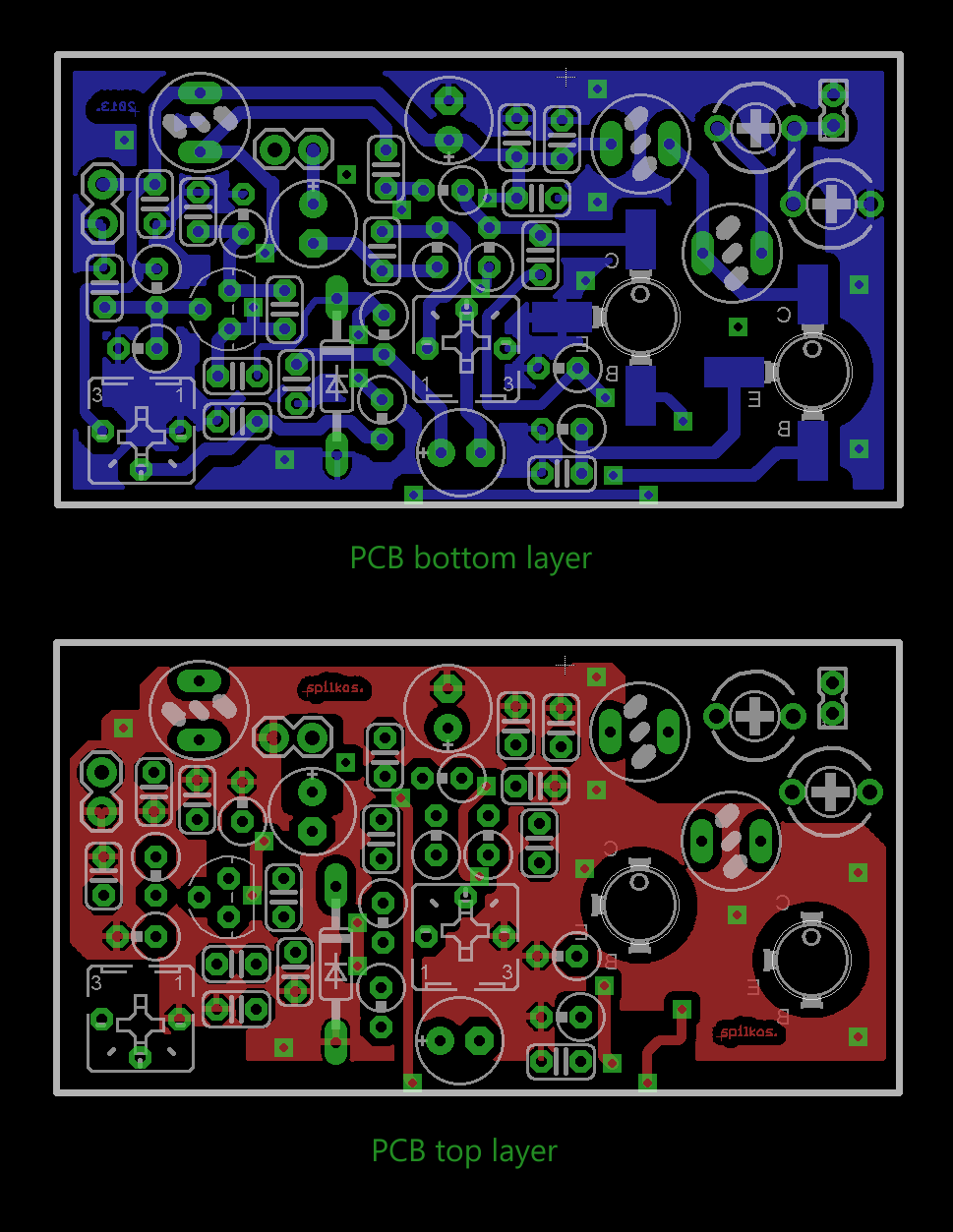
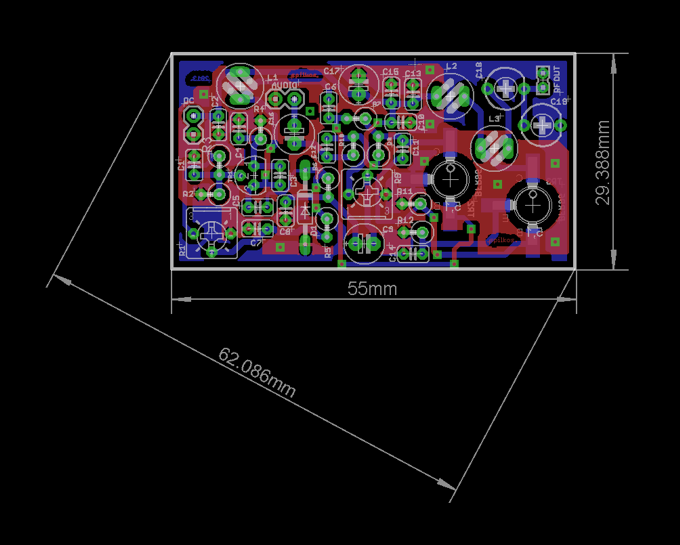
PCB


Subscribe
Login
0 Comments