

Digital Room Thermometer
- Rajendra Bhatt
- rajbex@yahoo.com
- 28.588 Views
- moderate
- Tested
- 0 Likes

Introduction
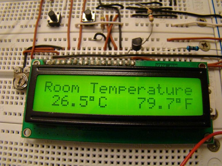
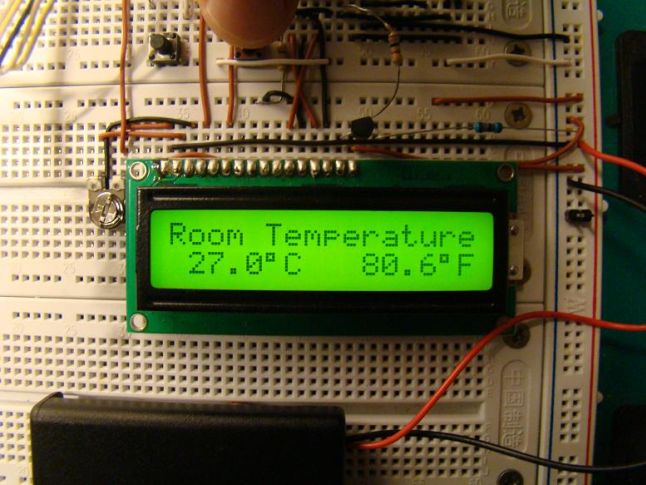
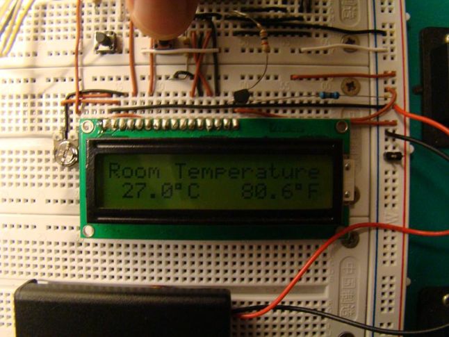
Room temperature plays a vital role in determining human thermal comfort. This digital thermometer is designed to measure room temperature and display it on a LCD screen in both Celsius and Fahrenheit scales. A PIC16F688 microchip is used as the main controller that reads temperature from DS1820, a 3-pin digital temperature sensor from Dallas semiconductors (now Maxim). The sensor is designed to measure temperature ranging from -55 to +125 °C in 0.5 °C increments.
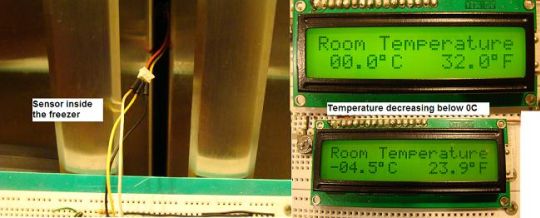
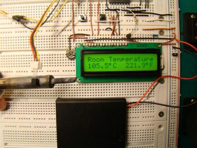
The room temperature doesn’t go that far but the firmware written for the PIC is able to read and display the entire temperature range of DS1820. I have tested it from -4.5°C (my freezer temperature) to 105.5 °C (by bringing a soldering iron tip close to the sensor). If you want to measure your freezer temperature too, don’t put the entire unit inside it, as some of the components (like LCD) may not work at that low temperatures. Rather put only the sensor inside the freeze and connect it to the rest of the system through three wires.
About DS1820
For a better understanding of how DS1820 sensor works, I recommend to read the datasheet from Maxim website. Remember that DS1820 and DS18B20 (both are temperature sensors) have architectural differences, and so DS18B20 will not work here. This project works with DS1820, and it would work with DS18S20 (later version of DS1820) too by changing the temperature conversion time in the firmware. Read this to find the difference between DS1820 and DS18S20, http://www.maxim-ic.com/datasheet/index.mvp/id/3021
The temperature reading from DS1820 is 9-bits which are read by PIC16F688 in two bytes (TempH and TempL), and then are combined into one 2-byte integer. In order to avoid floating point math during C to F conversion, the temperature value is first multiplied by 10. For example, 24.5 C becomes 245. Now C to F conversion is fairly easy.
TempinF = 9*TempinC/5 + 320 = 761 (which is 76.1 F)
The negative temperatures are read in 2’s complement form, so if the most significant bit of the 2-byte temperature reading from DS1820 is 1, it means the temperature is below 0°C. The firmware takes care of all negative temperature readings (in both C and F scales). The computed temperature is displayed on LCD as a 5 digit string array, xxx.x (e.g., 24.5, 101.0, -12.5, etc).
Circuit Diagram
PIC16F688 reads data from DS1820 sensor through RA5 port, and the computed temperature is sent to the LCD through RC0-RC3 ports. It means the data transfer from PIC to LCD is achieved in 4-bit mode. The Register Select (RS) and Enable (E) signals for LCD are provided through ports RC4 and RC5. The Read/Write pin of the LCD is grounded as there is no data read from the LCD in this project. The contrast adjustment of LCD is done with the 10K potentiometer shown in the circuit diagram.
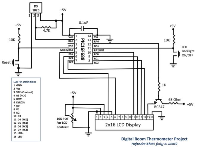
There are two tact switches for user inputs. The first one is the reset switch which, when pressed, will reset the whole system and reinitialize the LCD. The another tact switch connected to the external interrupt pin of PIC16F688 is for turning the LCD back light ON and OFF. In low illumination condition, the in-built LCD back light can be toggled by pressing this switch. An interrupt service routine is written for back light toggling. When the system is first turned ON, the LCD back light will turn ON too.
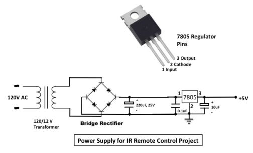
The following circuit can be used to get +5V regulated power supply required for the circuit.
Firmware
The firmware was developed on mikroC compiler. The in-built libraries for DS1820 makes the firmware development easier. The code is provided with adequate comments so that the reader won’t have much difficulty in understanding programming logic. The PIC microcontroller uses internal oscillator at 4.0 MHz. In the Edit Project window of mikroC, select internal clock, MCLR enabled, WDT Disabled, and Power On Timer Enabled.
/*
  Digital Room Thermometer using PIC16F688
  Copyright@Rajendra Bhatt
  July 13, 2010
*/
 // LCD module connections
sbit LCD_RS at RC4_bit;
sbit LCD_EN at RC5_bit;
sbit LCD_D4 at RC0_bit;
sbit LCD_D5 at RC1_bit;
sbit LCD_D6 at RC2_bit;
sbit LCD_D7 at RC3_bit;
sbit LCD_RS_Direction at TRISC4_bit;
sbit LCD_EN_Direction at TRISC5_bit;
sbit LCD_D4_Direction at TRISC0_bit;
sbit LCD_D5_Direction at TRISC1_bit;
sbit LCD_D6_Direction at TRISC2_bit;
sbit LCD_D7_Direction at TRISC3_bit;
// End LCD module connections

// Back Light Switch connected to RA1
sbit BackLight at RA1_bit;
// Define Messages
char message0[] = "LCD Initialized";
char message1[] = "Room Temperature";

// String array to store temperature value to display
char *tempC = "000.0";
char *tempF = "000.0";

// Variables to store temperature register values
unsigned int temp_whole, temp_fraction, temp_value;
signed int tempinF, tempinC;
unsigned short C_Neg=0, F_Neg=0, TempH, TempL;

void Display_Temperature() {
  // convert Temp to characters
 if (!C_Neg) {
     if (tempinC/1000)
   // 48 is the decimal character code value for displaying 0 on LCD
     tempC[0] = tempinC/1000  + 48;
     else tempC[0] = ' ';
  }
  tempC[1] = (tempinC/100)%10 + 48;             // Extract tens digit
  tempC[2] =  (tempinC/10)%10 + 48;             // Extract ones digit

  // convert temp_fraction to characters
  tempC[4] =  tempinC%10  + 48;         // Extract tens digit

  // print temperature on LCD
  Lcd_Out(2, 1, tempC);

  if (!F_Neg) {
     if (tempinF/1000)
      tempF[0] = tempinF/1000  + 48;
     else tempF[0] = ' ';
  }

  tempF[1] = (tempinF/100)%10 + 48;             // Extract tens digit
  tempF[2] =  (tempinF/10)%10 + 48;
  tempF[4] =  tempinF%10  + 48;
  // print temperature on LCD
  Lcd_Out(2, 10, tempF);
}

// ISR for LCD Backlight
void interrupt(void){
  if (INTCON.INTF == 1)          // Check if INTF flag is set
     {
     BackLight =~BackLight;  // Toggle Backlight
     Delay_ms(300) ;
     INTCON.INTF = 0;       // Clear interrupt flag before exiting ISR
     }
}

void main() {
  TRISC = 0x00 ;
  TRISA = 0b00001100; //  RA2, RA3 Inputs, Rest O/P's
  ANSEL =   0b00000000;
  PORTA =   0b00000000;            //  Start with Everything Low
  PORTC =   0b00000000;            //  Start with Everything Low
  CMCON0 =  0b00000111;
  Lcd_Init();                        // Initialize LCD
  Lcd_Cmd(_LCD_CLEAR);               // CLEAR display
  Lcd_Cmd(_LCD_CURSOR_OFF);          // Cursor off
  BackLight = 1;
  Lcd_Out(1,1,message0);
  Delay_ms(1000);
  Lcd_Out(1,1,message1);             // Write message1 in 1st row
  // Print degree character
  Lcd_Chr(2,6,223);
  Lcd_Chr(2,15,223);
 // different LCD displays have different char code for degree
 // if you see greek alpha letter try typing 178 instead of 223

  Lcd_Chr(2,7,'C');
  Lcd_Chr(2,16,'F');

  // Interrupt Setup
    OPTION_REG = 0x00;   // Clear INTEDG, External Interrupt on falling edge
    INTCON.INTF = 0;     // Clear interrupt flag prior to enable
    INTCON.INTE = 1;     // enable INT interrupt
    INTCON.GIE  = 1;     // enable Global interrupts

  do {
  //--- perform temperature reading
    Ow_Reset(&PORTA, 5);      // Onewire reset signal
    Ow_Write(&PORTA, 5, 0xCC);   // Issue command SKIP_ROM
    Ow_Write(&PORTA, 5, 0x44);   // Issue command CONVERT_T
    INTCON.GIE  = 1;     // 1-wire library disables interrpts
    Delay_ms(600);
    Ow_Reset(&PORTA, 5);
    Ow_Write(&PORTA, 5, 0xCC);    // Issue command SKIP_ROM
    Ow_Write(&PORTA, 5, 0xBE);    // Issue command READ_SCRATCHPAD

    // Read Byte 0 from Scratchpad
    TempL =  Ow_Read(&PORTA, 5);
    // Then read Byte 1 from Scratchpad
    TempH = Ow_Read(&PORTA, 5);
    temp_value = (TempH << 8)+ TempL ;
    // check if temperature is negative
    if (temp_value & 0x8000) {
      C_Neg = 1;
      tempC[0] = '-';
      // Negative temp values are stored in 2's complement form
      temp_value = ~temp_value + 1;
      }
    else C_Neg = 0;
    // Get temp_whole by dividing by 2
    temp_whole = temp_value >> 1 ;
    if (temp_value & 0x0001){  // LSB is 0.5C
       temp_fraction = 5;
       }
    else temp_fraction = 0;
    tempinC = temp_whole*10+temp_fraction;

    if(C_Neg)  {
     tempinF = 320-9*tempinC/5;
     if (tempinF < 0) {
      F_Neg = 1;
      tempF[0] = '-';
      tempinF = abs(tempinF);
      }
     else F_Neg = 0;
     }
    else tempinF = 9*tempinC/5 + 320;
    //--- Format and display result on Lcd
    Display_Temperature();

  } while(1);
}
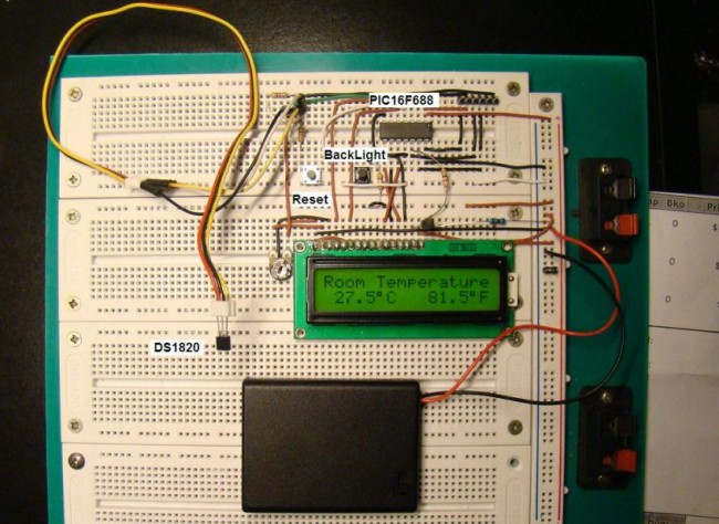
Snapshots of temperature measurements

Please follow and like us:


Thanks for the project, its really nice. I have built this and its working fine except one thing- it shows temp in four digits, for ex – 248.3 C
where actual temp should be 24.8 C. I have not made any changes to the code and i just used hex file. May I request your help how can fix it please.
I have noticed, below values/format has been mentioned in the program code (Apologies, i am not very good with programming)
// String array to store temperature value to display
char *tempC = “000.0”;
char *tempF = “000.0”;
Is this the cause? May i request your help in completing this project successfully please 🙂
Awaitng reply.
Check out the sensor connections to make sure it is working. The code should work just fine for that value of temperature.
Thanks for your reply. I got the issue. My vendor given me DS18B20 instead of DS1820. Can you help me with hex file for this circuit with DS18B20 sensor please. It will be really great help for me as DS1820 manufacturing has been stopped now.
Thanks in advance 🙂