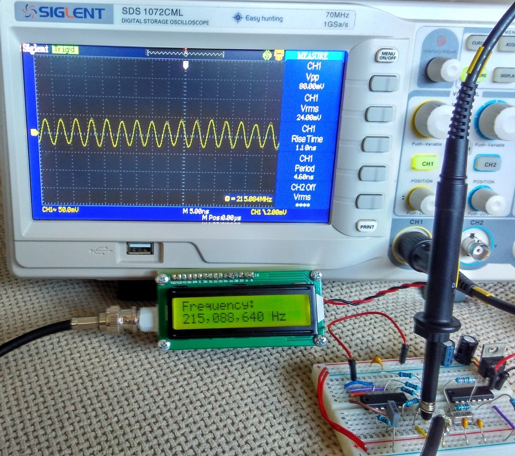
This project shows how to build a very simple yet very useful tool that every DIY enthusiast should have in his lab: a 100MHz+ frequency counter.
The schematic is fairly simple and straightforward and uses a PIC16F628A microcontroller for measuring frequency and a high speed comparator for signal amplification and conditioning.
The microcontroller uses its internal 4MHz oscillator for the CPU clock. Timer1 uses an external crystal resonator (watch crystal) with 32768Hz frequency for setting the 1 second time base.
Timer0 is used to count the input signal at pin RA4.
100MHZ Frequency Counter with PIC16F628A – [Link]




Hi,
congratulations , this seems a really interesting project and i would like to implement it in another one that i’m working in. Just a simple question since i’m new in Micro World. What i should add to the code to have an RS232 output directly to a serial?
Thanks in advance.
To achieve serial communication from this counter you have to modify source code to enable serial communication on TX/RX pins of the microcontroller. This is not so hard for someone who knows PIC mcu programming, you may contact the author for modification of this project.