7-segment Display Counter
- Muhammad Shahid
- m_shahid@live.co.uk
- 15 min
- 26 Views
- 0 Comments
Introduction
7-segment Displays can be combined to show the numbers 0 through 9 along with a few other characters for use in a counting circuit or to interact with a microcontroller.
With microcontrollers like the Arduino or Raspberry Pi and little code, it is now quite simple to display letters and numbers across several LED displays. However, as students or enthusiasts of electronics, we may wish to show two or more numbers or digits as part of a digital logic circuit or project.
7-segment displays, which are essentially made up of a load of light-emitting diodes attached within a single indicator package, offer a practical means of showing numerical information from zero to nine.
An electrical current is used to illuminate each light-emitting diode, also known as a segment. By illuminating different combinations of segments, we may display specific letters or numerals by turning certain segments “ON” and generating light while turning others “OFF.”
LEDs are similar to regular diodes in that they only permit current to travel in one direction. The distinction between the two is that when an electrical current flows through an LED, light is released from the PN junction.
When the LED’s Anode (A) terminal is about 2 volts more positive than its Cathode (K) terminal, this electroluminescence process takes place. Typically, a resistor connected in series with the LED is used to regulate the supply current needed to illuminate an LED junction, which ranges from around 6mA to 20mA.
Therefore, we can create a series of randomly lighted segments or a decimal number from 0 to 9 as a visual output for our project by forward biasing any one of the display LED segments such that the anode terminal is towards the supply (positive) and the cathode terminal is towards the ground (negative).
7-Segment Display
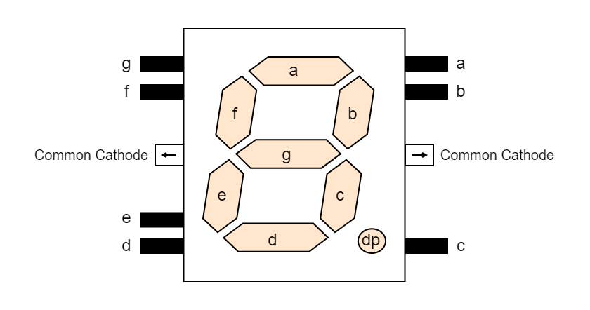
As the name implies, a 7-segment display has seven segments, which are made up of seven light-emitting diodes, or LEDs, that when combined make a single full number on the screen.
Since the eighth LED is utilized for a decimal point, typically in one of the lower corners of the display, the majority of seven-segment displays have eight internal LEDs.
Does this imply that each 7-segment display will have 14 connection pins or terminals if it contains seven LEDs (for now forgetting the decimal point), one for each segment, and each LED has two terminals, an Anode and a Cathode? The answer, however, is No.
One terminal of each internal LED is linked to a common point or node, however individual LED segments can be lighted as needed. Therefore, we will only have eight (7 + 1) connecting pins instead of 14; one for each of the seven distinct LEDs and a common pin, which is the “common pin” that indicates the kind and name of the 7-segment display.
A display is called a Common-Cathode (CC) display when the cathode terminals of every LED used in it are shorted together. Similarly, a display is called a Common-Anode (CA) display when all of the anode terminals of the LEDs used in it are shorted together. There are two types of 7-segment displays: Common Cathode (CC) and Common Anode (CA).
Common Cathode (CC) Configuration

The Common Cathode (CC) Display – All of the cathode (K) connections of the LED segments are hooked together and connected to ground or zero volts in a common cathode (CC) display.
By forward biasing the individual anode terminals (a to g) with an appropriate electric current, the individual segments are lighted. For a common cathode display to function, a drive circuit that can supply current is necessary.
Common Anode (CA) Configuration

The Common Anode (CA) Display – All of the LED segments’ anode (A) connections are connected to a positive voltage source in a CA display.
Applying a ground, or “LOW,” signal to the specific segment’s cathode terminal (a to g) illuminates each segment. Therefore, a driving circuit that can sink a current is necessary for a common anode display.
Multiple 7-segment LED displays can be connected to an electrical circuit in a variety of ways, each with unique benefits. Since there are seven segments (plus a decimal point) and each segment needs around 6 to 20 milliamperes (mA) of electricity to light it to normal brightness, each display is often driven directly by specialized decoder/driver circuits.
A variety of digital decoders are available based on the kind of input data (binary, BCD, or hex) and the required output code, which indicates the number of decoded output lines. IC decoder chips essentially convert one type of input data into another. 3-to-8 lines, 4-to-16 lines, etc. are a few examples.
In our situation, a “BCD-to-seven-segment decoder”—a decoder chip that can translate binary code into a set of output signals—is needed to operate a seven-segment display. The following list of IC decoder chips can represent the 10 decimal digits from 0 to 9 using a set of 4-bit binary digits known as Binary Coded Decimal, or BCD for short.

The most widely used 7-segment decoder integrated circuit (IC) that can power common anode (CA) displays is the TTL 74LS47. Each of the seven LED segments may be driven by the TTL 74LS47’s seven separate active “LOW” outputs and 4-bit BCD input.
An LED segment is illuminated by an active “LOW” output, which causes the output pin to flip to ground (0V); an LED segment is turned “OFF” by an active “HIGH” output. While any common anode display will work (and there are many to select from), the HDSP series of displays is a nice place to start.
Four switches are used to apply a 4-bit binary number to the 74LS47 decoder’s BCD inputs A, B, C, and D. This results in the output signals a, b, c, d, e, f, and g, which are then used to drive the 7-segment display to create the necessary numbers from 0 to 9 as shown.
The 74LS47 Decoder
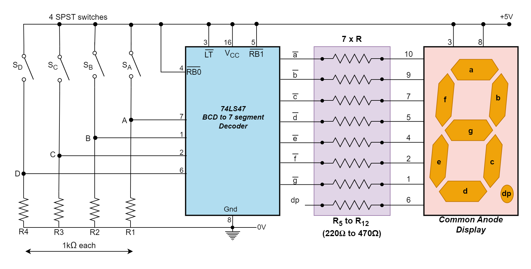
Seven resistors are needed to limit current flow between the 74LS47 decoder/driver and the common anode display (eight if the decimal point is added). The current flowing through each LED segment of the display must be carefully regulated for each section to light up correctly.
Using a current-limiting resistor in series with each of the seven LED segments, as illustrated, is the most effective way to limit the current flowing through a display section. Without a resistor linked in series, the maximum current would flow and the LED would briefly become very bright before being destroyed.
A typical 7-segment LED display has a voltage drop across the diode junction of the LED of around 1.8 volts for normal brightness, with each LED segment rated to run at 6 mA to 20 mA. The current-limiting resistor value required to provide the necessary current per LED section may be determined.
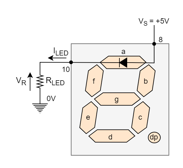
Hopefully, we now know that a seven-segment display is a collection of separate LEDs in a single rectangular package and that each segment’s DC forward current must be limited by a series resistor.
Each LED segment’s anodes are coupled to a 5-volt supply (VS) in a common-anode display. The voltage across the series resistor must also be identical if the forward voltage drop across the LED’s junction is about 1.8 volts when illuminated: VS – VLED = 5 – 1.8 = 3.2 volts.
Therefore, Ohm’s Law can be used to easily determine the resistive value needed for the series current limiting resistor of a single segment at the necessary current flow to illuminate it. As a result, we can determine the range of resistance needed to keep the LED’s current within the 6mA–20 mA range for every given application and desired LED intensity as follows:
7-segment Display Resistor Values

Therefore, for a 6mA current, we would need a series current limiting resistor of 533Ω, or 560Ω to the closest desired value, and a resistor of 160Ω to restrict the current to 20mA. In actuality, a 7-segment display might be illuminated from a 5-volt supply using any decent standard recommended resistor value between 220Ω and 360Ω; it all depends on the resistor values you have on hand.
The same calculations and resistive values apply to common cathode LED displays as well, even though we are using a common anode LED display as our example here. Commonly available dual-in-line package (DIP) resistor networks simplify the wiring procedure between the driver IC and display by including all seven (or eight) resistors in a single DIP package.
It should be noted that although the TTL 74LS47 BCD to 7-segment decoder/driver IC was utilized in this instance to drive a common anode display through its active LOW (current sink) outputs, the TTL 74LS48 BCD to 7-segment decoder/driver IC is identical, with the exception that it is made to drive a common-cathode display because it generates active HIGH (current source) outputs.
Therefore, the type of 7-segment LED display you have will determine whether you require a 74LS47 IC for driving, such as an LT542 CA display, or a 74LS48 IC for driving the LT543 CC display, which is its counterpart.
Displaying Numbers on a 7-segment Display
The 74LS47 includes outputs for each of the seven-segment display segments and four inputs for the BCD (8-4-2-1) digits A, B, C, and D.
When the four switches SA, SB, SC, and SD are used, the required input sequence will be produced, activating the relevant LED segments that display the associated number. The +5V supply (HIGH) is connected to the 74LS47’s LT (Lamp test), BI/RBO (Blanking Input/Ripple Blanking Output), and RBI (Ripple Blanking Input) for regular functioning. As a result, the following numbers are shown:

It can be a little tiresome to operate all four SPST switches at once, even if doing so will cause the matching numbers or random characters to appear. Thus, it would be preferable if we had a single integrated circuit (IC) chip—the 74LS90 BCD Counter—that could produce 4-line binary data without the need for four switches.
To generate a BCD output code, the 74LS90 integrated circuit may be set up as a MOD-10 decade (divide-by-10) counter. It counts from 0000 to 1001 before resetting to 0000. This asynchronous decade counter/divider integrated circuit allows us to increase the numbers on the seven-segment display with a single switch, as demonstrated.
Single Digit 7-segment Display Counter

By simply pressing one pushbutton switch, SW1, 10 times, we can now increase the numbers on the display from 0 to 9. The count may be altered to change when the pushbutton, SW1, is released or activated by adjusting the pushbutton’s location and the 1kΩ resistor.
Our straightforward design demonstrates how to use a 74LS90 BCD Counter and a 74LS47 7-segment display driver to create a 0 to 9 digital counter. However, a second counter stage can be added to this single-digit 0–9 counter to create a two-digit 00–99 counter.
Two Digit 7-segment Display Counter

So, how does this seven-segment, two-digit display counter operate? Except for the fact that pressing the pushbutton SW1 causes the “one’s” (also known as “units”) LED display to increase, the first half of the digital counter circuit functions as previously.
With every closing (trailing-edge) of SW1, the first 74LS90 BCD counter, U1, counts upward from 0 to 9 (0000 to 1001). Pin 11 of U1, which corresponds to output “D,” goes “HIGH” when the counting sequence reaches “8” (1000) on the one’s display. It remains HIGH until U1 resets itself back to zero on the tenth count, at which point pin-11 of U1 goes “LOW” once more.
Each successive HIGH/LOW switching action of pin-11 (output D) of U1 increases the second LED display for the ten digits since it is linked to the clock A (CLKA) input pin-14 of the second 74LS90 BCD counter U3. As a result, when the two LED screens are positioned next to each other, they count up from 00 to 99 before returning to 00 for the subsequent count.
There are several uses for this basic digital counting circuit in school projects. For instance, we might use a sensor to count moving objects, people, automobiles, etc. in place of the manually controlled pushbutton switch, SW1. For instance, SW1 might be used as a basic 2-digit timer or response timer circuit with or without the decimal point, or it could be substituted with a 555 timer or astable oscillator circuit to count a series of pulses.
Although the 74LS90 decade (divide-by-ten) counter and the aforementioned 2-digit counter circuit work well together, we require two of them, U1 and U3. The TTL 74LS390 and its CMOS counterpart, the 74HC390, are more affordable than purchasing two 74LS90s because they combine two 74LS90 decade counters into a single integrated circuit package.
Similar to the single 74LS90, the TTL 74LS390 4-bit decade counter features two internal divide-by-two and divide-by-five counters that may be set up as divide-by-multiples of “2, 5, or 10” with a BCD output. One 74LS390 IC, with each half of the IC driving one of the LED displays, can therefore be used in place of the two 74LS90 ICs U1 and U3 in the prior circuit.
Improved Two Digit Counter

A 74LS390 BCD Counter and two 74LS47 7-segment display drivers are used in the design to demonstrate a basic 00 to 99 digital counter. We would need to cascade more counter-circuits together to count over 99.
In decimal, a 4-digit BCD counter would count from 0000 to 9999 before resetting to 0000. Similarly, three cascaded decade counters are needed if we wish to count from 0 to 999999. As demonstrated, it is indeed possible to create several decade counters by simply cascading together separate BCD counter circuits, one for each decade.
Cascading Counters
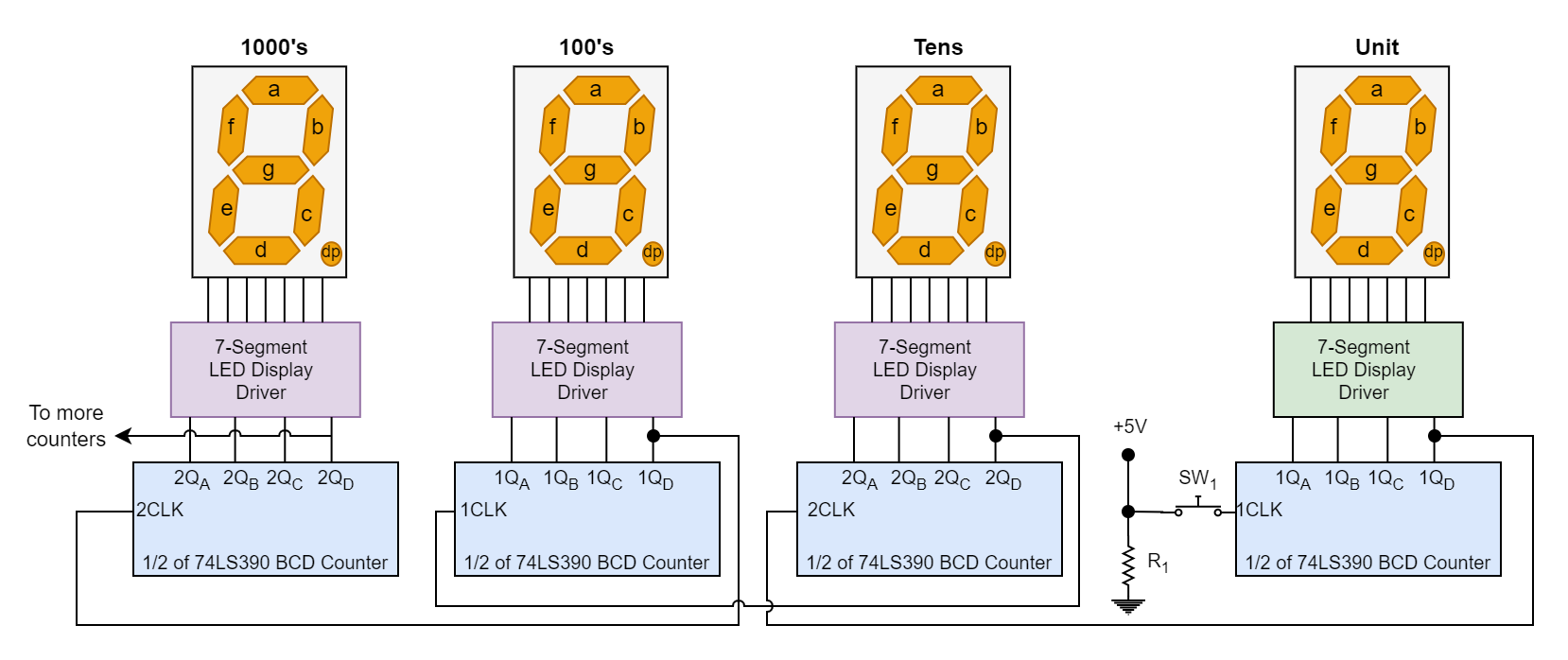
As demonstrated in this lesson on the 7-segment Display Counter, conventional combinational logic circuits (ICs) may be used to build LED display decoder circuits, and there are several specialized ICs available on the market to carry out this task.
Along with its CMOS counterparts, display decoder integrated circuits (ICs) like the 74LS47 Seven-segment decoder/driver IC for driving a common anode (CA) display and the 74LS48 Seven-segment decoder/driver IC for driving a common cathode (CC) display are widely available.
To generate a BCD output code, the 74LS90 asynchronous counter IC may be set up as a MOD-10 decade (divide-by-10) counter. It will count up from 0000 to 1001 before resetting to 0000 to begin the cycle over.
An extremely versatile counting circuit, the 74LS90 BCD Counter may be configured to divide any whole number count from 0 to 9 for a single display or to function as a frequency divider.
We can create a two-digit counter by cascading two 74LS90 counters together, but much better, we can create an unlimited number of counter stages using multiple 7-segment LED displays by utilizing the dual decade/driver IC 74LS390.
Summary
- A 7-segment display consists of seven LEDs arranged to form digits 0–9 and other characters. Each segment can be individually lit by controlling current through the LEDs. The display also includes an optional eighth LED for a decimal point.
- In Common Cathode (CC) displays, all cathodes are connected to the ground, and individual segments are activated by applying current to their anodes. In Common Anode (CA) displays, all anodes are connected to a positive supply and individual segments are lit by grounding their cathodes.
- A 74LS90 BCD Counter can be used to generate a 4-bit binary output for driving a single 7-segment display. It counts from 0 to 9 and resets to 0, making it suitable for simple counting applications.
- By cascading multiple counters, multi-digit displays can be created. For example, two 74LS90 ICs can create a 2-digit counter (00–99), while the dual-counter IC 74LS390 provides a compact solution for similar tasks.
- 7-segment displays and associated counter circuits are widely used in digital clocks, calculators, counters, and measuring devices. The circuits can be modified for more digits or enhanced using sensors, 555 timers, or frequency dividers to expand their applications.


