AC Capacitance and Capacitive Reactance
- Boris Poupet
- bpoupet@hotmail.fr
- 12 min
- 5.271 Views
- 0 Comments
Introduction
Such as for inductors, the electrical behavior of capacitors also depends on the nature of the source : DC or AC. We will see through this tutorial that in some way, the capacitor can be seen as the opposite of an inductor in terms of frequency functioning.
Like for the resistors and inductors, we present in a first section the concept of capacitance that will help us to understand why capacitors behave differently in DC and AC regime and by which mechanisms they do it.
In the second section, we talk about the capacitive reactance to understand exactly how capacitors react with an increase of the frequency.
The last section shows how associations of resistors-capacitors or inductors-capacitors work and can be used for filtering applications.
Presentation
The Capacitance
The capacitance (C) is a primary concept to understand on how a capacitor works. It describes the voltage (V) that the component will generate when charged with electrical charges (Q) at its terminals. The most general and natural way to express the capacitance is therefore C=Q/V being expressed in Farad (F).
Before illustrating and giving more details about the capacitance, it is worth to briefly describe what is an electrical charge. Such as the concepts of mass and time, the charge is hard to describe with simple words, it is easy to feel but tricky to define. It is an intrinsic property of elementary particles such as electrons or protons.
When a charge moves it creates a current, the charge of electrons is equal to -e and for protons it is +e, opposite charges attract each other : this is why electrons orbit around atoms without escaping. The official unit to measure a charge is the Coulomb (unit C) and e≅1.6×10⁻¹⁹ C.
Measuring a charge is however not easy nor the method used to determine the capacitance of a particular component. Fortunately, the capacitance can be expressed with another formula presented in the following.
Unlike the resistivity and inductance, the capacitance strongly depends on the geometry considered. The most simple example of capacitor is the parallel plate topology represented in Figure 1. It consists of two conducting plates separated by a thin layer of insulating material (in green).
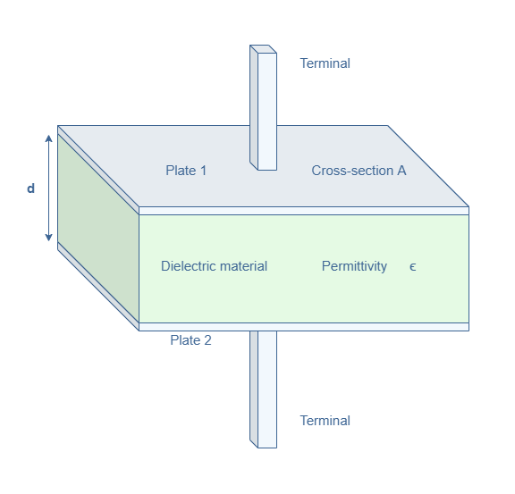
If a potential difference is applied between the plates through the terminals, a charge +Q (resp. -Q) will be formed in the plate 1 (resp. plate 2). The capacitance can in this case be expressed by the following formula :

ε is the absolute permittivity and can be decomposed in two factors : ε=ε0×εr with ε0≅8.8×10⁻¹² F/m being the vacuum permittivity and εr the relative permittivity of the insulating material. Materials with higher insulating properties have a higher relative permittivity which increases the capacitance.
In order to better understand these concepts and how capacitors work, we can define an hydraulic analogy with an elastic membrane inside a pipe such as shown in Figure 2. Hydraulic analogies are a common way to establish correlations between abstract concepts in electricity with a more simple approach in the hydraulic domain.
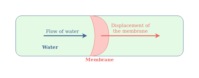
In this analogy, the pipe represents the electric wire, the flow of water represents the electricity and the membrane is the capacitor. Moreover, the stiffness of the membrane represents the capacitance.
Such as for the capacitor, the water cannot go through the membrane but its pressure (analogy of the potential) induces a displacement of the membrane. If the water pressure is kept constant in the same direction, the membrane is pushed in the same direction with the same curvature and the molecules of water do not move. However, if an alternating flow of water is given, the membrane is pushed alternatively in opposite directions and the molecules of water are moving around it.
DC and AC regimes
Now that we know more deeply what a capacitance consists of, we need to understand why it’s behavior is different when applying a constant or alternating voltage, which we briefly explained with the hydraulic analogy. Consider the same architecture of capacitance C as presented in Figure 1 when applying a constant potential difference V-VGROUND :
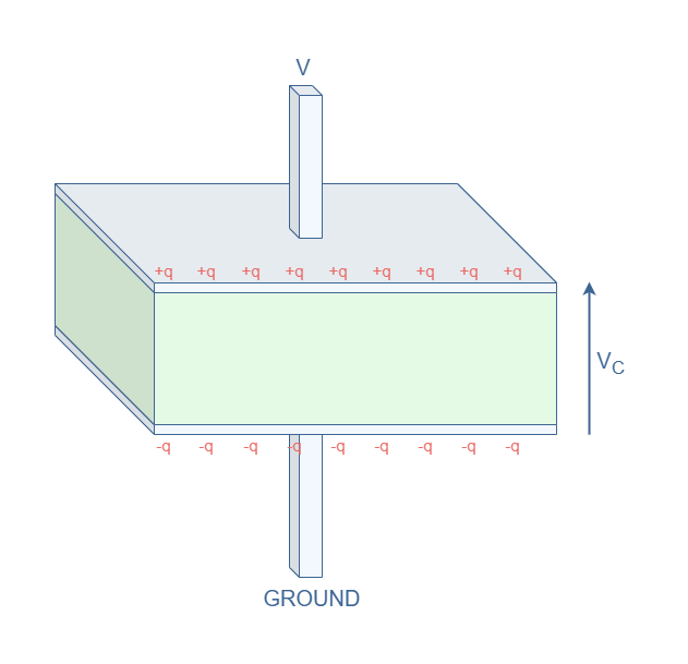
Due to electrostatic effect, applying a positive voltage V attracts charges +q at the plate 1 and -q at the plate 2. The sum of the positive charges (resp. negative charges) is +Q (resp. -Q). This distribution of charges generates a voltage VC=Q/C in the capacitor.
As long as the capacitor holds the charges, the voltage VC remains stable and we describe this particular state as charged. For perfect capacitors, the voltage VC can remain even if the DC source is turned off. However, in reality, we observe a discharge when the charges redistribute and VC decreases exponentially.
Apart from a temporary current that can be observed when the capacitor discharges (if the source is turned off), IC=0 in DC regime.
This behavior is however different in AC regime, the Figure 4 below superimpose the voltage and current characteristic along with the distribution of charges in the capacitor :
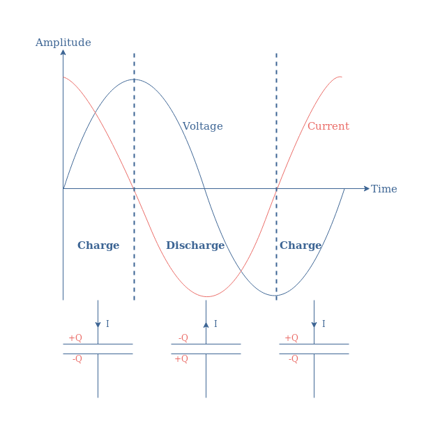
When applying an AC voltage to a capacitor, charge and discharge cycles are observed which generates a current that is phase shifted of -90° which is known as a quadrature of phase delay.
Another more mathematical way to understand the appearance of a current when the frequency increases is with the general relation C=Q/V that can be rewritten V=Q/C.
This relation is differentiable such as shown in the following equation :

By definition dQ/dt=I, therefore, the current (I), voltage (V) and capacitance (C) are linked by the following equation :

With the Equation 2, we can see that no current can be observed if no variation of voltage is present. Moreover, the current increases if the variations are faster, i.e if the frequency increases.
Frequency behavior
Such as for inductors, the concept of reactance can also be applied for capacitors. It is noted XC and describes the opposition of a capacitive component with a change of voltage. The capacitive reactance is the imaginary part of the complex impedance ZC of a capacitive component : ZC=RC+j×XC.
Actually, the impedance of a capacitor reduces to –jXC since we have seen previously that the phase shift observed in a capacitive component is -90°. We can refer to the tutorial about complex numbers to understand that such a phase shift is only possible if the complex impedance is a pure imaginary number, giving therefore RC=0.
The capacitive reactance satisfies the following Equation 3 :
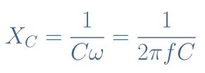
As opposition to the inductors, we can understand through this equation that the opposition to an AC voltage decreases inversely with an increase of the frequency. At f=0, XC→+∞, which means that the capacitor behaves as an open circuit at low frequency. When f→+∞, XC=0, which means that the capacitor becomes a short circuit.
Filters
The different properties of the three basic electric components (R, L and C) can be associated in the same circuit to create filters. In this section, we briefly present the RC and LC filters.
RC filter
Consider the following circuit in Figure 5 with Vin the input voltage and Vout the output voltage :
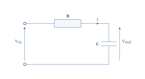
We use the same technique as shown in the AC inductance tutorial in order to get the gain and phase shift of the circuit with the transfer function.
By applying the voltage divider formula, we get the following transfer function TV :
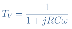
And finally the gain and phase shift of the RC filter is given by |TV| and Φ :

We can plot these two quantities on a Bode diagram by choosing for example R=100 Ω and C=1 μF :
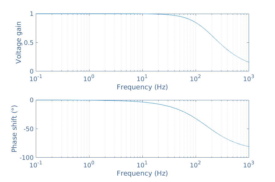
From the Bode diagram, we can observe that the RC series circuit is a low-pass filter since at low frequencies, the gain is equal to 1 and when the frequency increases, the gain tends to 0.
LC filters
The association of an inductor with a capacitor is more interesting because a completely opposite behavior appears when connected in series or parallel, which isn’t the case for the RC filter.
Let’s first of all consider the series circuit such as represented in Figure 7 :
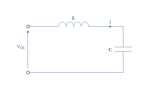
The total impedance Z is given by Z=ZC+ZL=jLω+(1/jCω). We can rewrite this expression with a common denominator, and by defining the quantity ω0=1/√(LC), it comes :
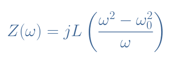
We can see that Z(ω0)=0, for this reason, ω0 is named the resonance frequency. When connected with a load, an LC circuit will behave as a band-pass filter around ω0.
The parallel circuit represented in Figure 8 behaves exactly at the opposite of the series circuit.
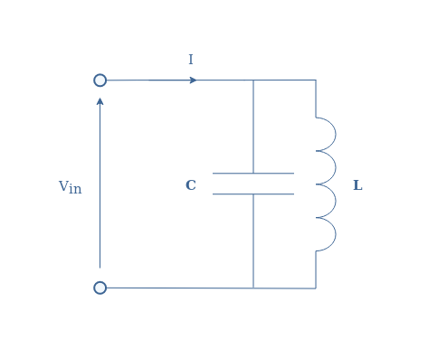
With the same method as exposed previously, the total impedance can be written such as :

Here however, Z(ω0)→+∞ which means that at the resonant frequency, the circuit behaves as an open circuit. When connected with a load, the LC parallel filter act as a band-stop filter around ω0.
Conclusion
We have first presented the concept of capacitance in order to understand better how capacitors works. The capacitance reflects the opposition of current that a component creates due to a change of voltage. We have seen that in DC regime, a capacitor just stores energy in the form of charges with no current being observed. The charges can however be released if a change of voltage happens : this is the case in AC regime.
By describing the capacitive reactance, we have seen that the opposition to the current of a capacitor depends inversely with the frequency. In DC regime, the capacitor is an open circuit and as the frequency increases, it becomes a short circuit.
Finally, the association of resistors and inductors with capacitors can create interesting filters. The RC series circuit is a low-pass filter : it attenuates high frequencies. The LC series circuit is a band-pass filter : it attenuates the frequencies out of a certain band around the resonance frequency. The LC parallel circuit is a band-stop filter : it attenuates the frequencies within a certain band around the resonance frequency.


