

Electric Potential In Uniform Fields
- Kamran Jalilinia
- kamran.jalilinia@gmail.com
- 12 min
- 62 Views
- 0 Comments
- 0 Likes

Electric Field Due To Uniformly Distributed Charges
Let’s consider a configuration of two nonconducting planes that are oppositely charged and placed in parallel to each other at a small distance. Suppose that the positive and negatively charged planes are set up facing each other.
Figure 1 shows part of two infinitely large, nonconducting plane sheets with two uniform distributions of positive and negative charges on one side.
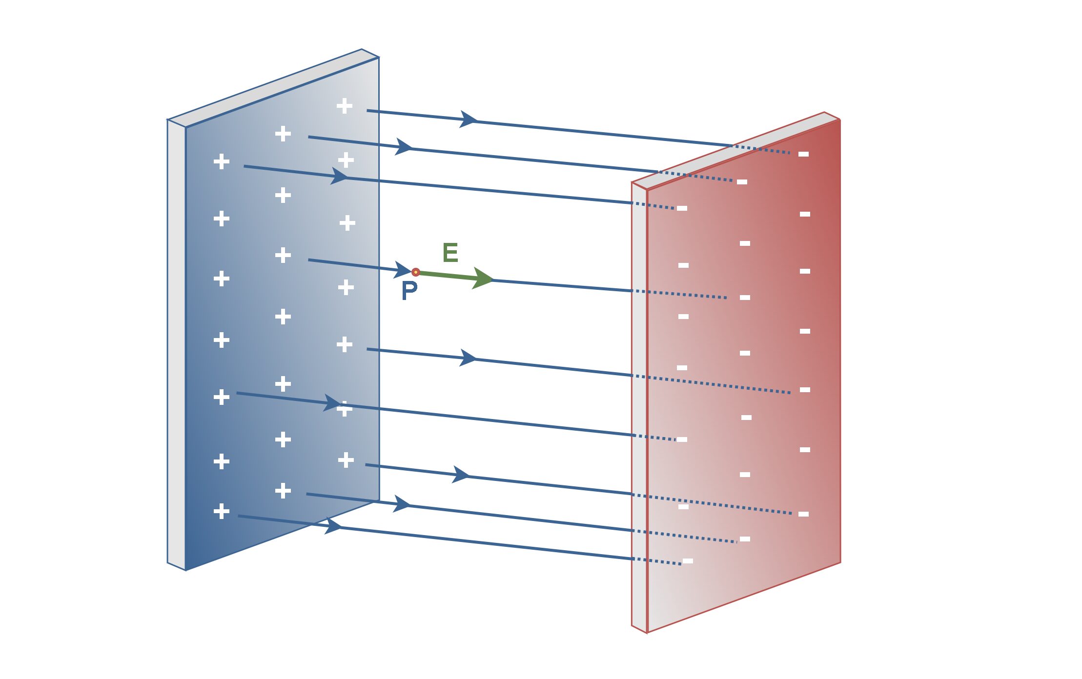
In this configuration, the lines of electric field E (blue lines) in the space between the planes would be regularly spaced. Note that some of the field lines are not plotted due to the simplicity of the figure.
The electric field E points away from the positively charged plane and toward the negatively charged plane. In this condition, the electric field has the same direction at every point within the field and the field lines are parallel and evenly spaced. This is called a uniform electric field that exists in a region between two oppositely charged planes with a uniform distribution of charges.
If we place a positive test charge at any point near the positively charged sheet, for example at point P, we find that the electrostatic force on the particle is outward and perpendicular to the sheet. Thus, the electric field vectors and the electric field lines must also be outward and perpendicular to the sheet, as shown in Figure 1.
In a uniform field, the field lines are parallel. This indicates that the electric field E is equal for all points at the same distance to the positive plane in the field.
Of course, there is no such thing as an infinitely large sheet in reality. This is just an assumption to say that we are physically measuring the field at points close to the plane relative to the size of the plane and that we are not near an edge.
Electric Potential In A Uniform Field
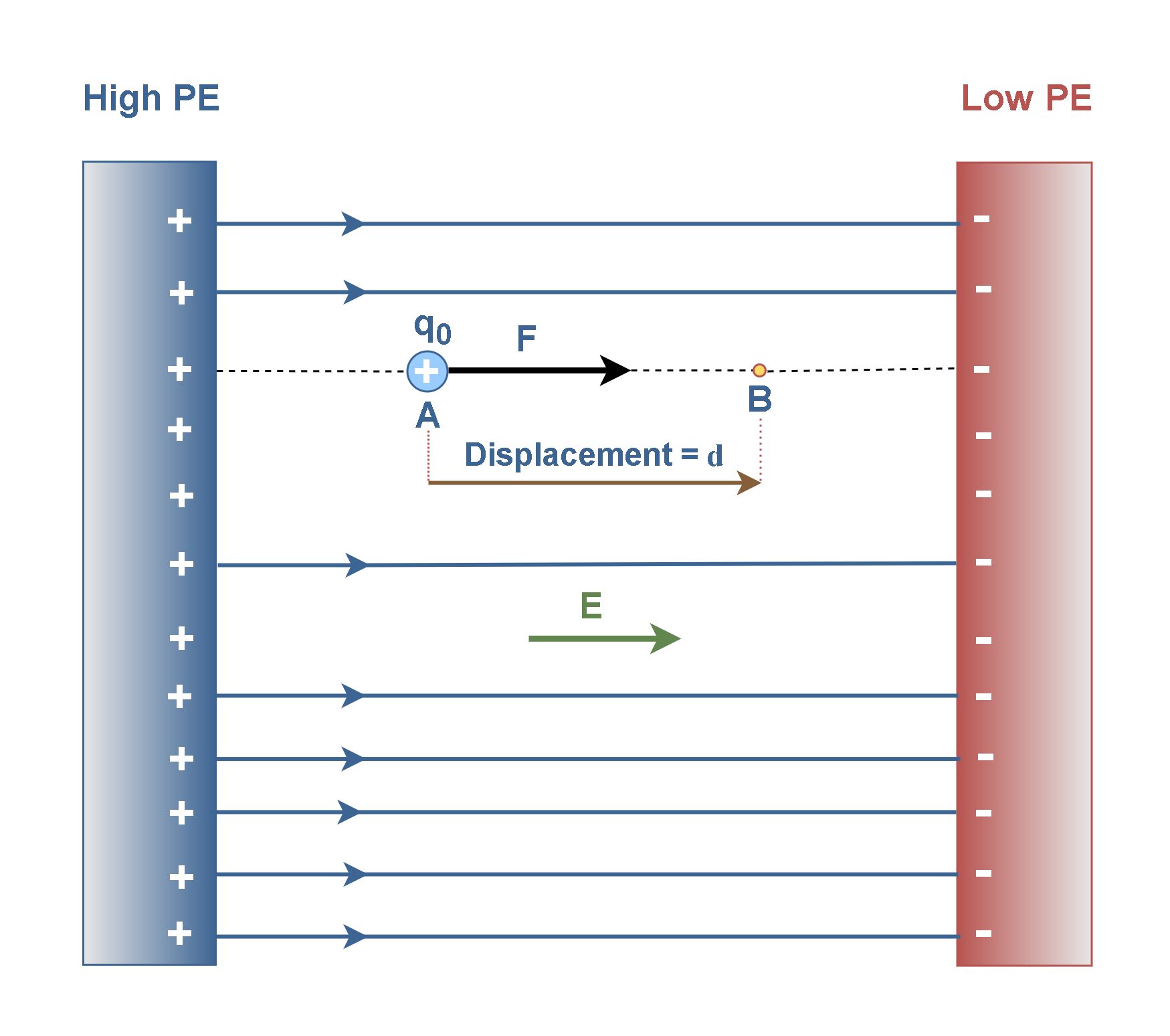
In the same structure of Figure 1, assume that a positive test charge q0 is placed at point A in a uniform electric field E, as shown in Figure 2. When this point charge is placed in such an electric field, we can predict it has a movement based on the electrostatic force F applied. Figure 2 shows that if a positive point charge q0 begins at rest in this rightward-pointing electric field, the point charge will move toward the right. If that point charge q0 is instead negative, the point charge will begin to move to the left, against the direction of the electric field.
Essentially, the electrostatic force F is conservative, which means that the work done on q0 is independent of the path taken. The work done by a conservative force depends only on the beginning and ending positions of the object. So, it is possible to define a potential energy associated with the force. The work done by a conservative force can be reinterpreted as the negative of the change in potential energy associated with that force.
In our case the force moves the positive charge q0 farther from the positive plane, and the electric potential energy of the charge q0 decreases. Because it moves from the positively charged plane with a higher level of potential energy (High PE) to the negatively-charged plane with a lower level of potential energy (Low PE).
As the charge moves from point A to point B under the influence of the electric field E, the work done on the charge by the electric field, WAB, is equal to the electric force F times the displacement d, in the same direction. Equation 1 calculates the physical work.

As we have already seen in the previous article, the electric potential difference ΔV between points A and B is the change in electric potential energy as a charge q0 moves from A to B divided by the charge q0. Equivalently, it can be defined by the work done on the charge q0 by the electric field.
Then, the potential difference ΔV between two points A and B in the uniform electric field is given by Equation 2.

Where E is the electric field vector and d is the displacement vector from point A to point B. In such a configuration, because vectors E, F, and d have the same direction, The dot products F.d and E.d give the scalar results, i.e., only magnitudes.
The negative sign Equation 2 indicates that the electric potential decreases in the direction of the electric field. This means that moving in the direction of the electric field corresponds to moving to a region of lower potential. Since the electric field is uniform, the rate of change of the potential concerning distance is constant. However, the work done on the test charge by the electric field is positive when it moves from higher to lower potential.
The familiar term voltage is the common name for electric potential difference. Whenever a voltage is quoted, it is understood to be the potential difference between two points. We have already mentioned that the SI unit of electric potential is ‘joules per coulomb’ or volts (V).
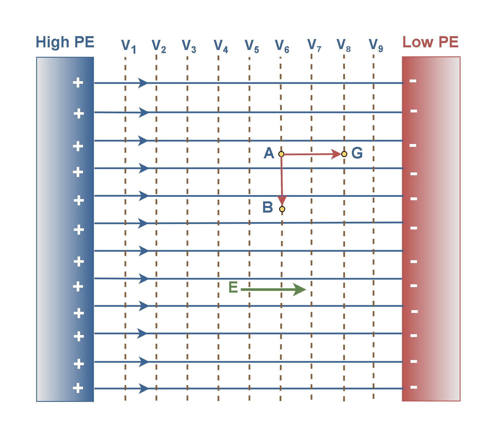
In a uniform field because of parallel and equal electric field vectors, the equipotential surfaces (which are orthogonal to the field lines) are equally spaced parallel to charged planes.
In Figure 3, the equipotential surfaces are plotted as parallel dotted lines for some equal distances between charged planes. Every line (surface) is assigned to an electric potential or voltage, as V1 to V9, i.e., different voltages in terms of different distances to the source of potential energy (High PE).
If we combine the results of Equation 1 and Equation 2, we find Equation 3:

Using this equation, we obtain the following general result: No energy is required to move a charge between two points that are at the same electric potential, like the path AB in Figure 3. Since ‘equipotential’ means that VB = VA and therefore, WAB = 0.
Work is done only when the object moves between equipotential surfaces, for example, the path AG in Figure 3.
Electric Potentials In Charged Conductors
A conductor can conduct, or convey, an electric charge. Metals such as copper, brass, aluminum, and silver are examples of conductors. A property of metal bodies is that they are good conductors of electricity and they readily permit a current flow or motion of charge in them.
If a conductor body is charged, the charges move in conductors until they reach an equilibrium configuration. Essentially, when a conductor is in electrostatic equilibrium, a net charge placed on it resides entirely on its outer surface. The charge in the conductor is distributed on the surface due to the electrostatic force of repulsion. The net charge inside the conductor is zero.
In static situations, a conductor may be defined as a medium in which the electric field is always zero. In this case, the electrostatic field at the surface of a charged conductor has always a direction normal to the surface. Therefore, if a conductor body is charged, the electric potential at all points on a charged conductor is the same. Thus, all of its outer surface can be considered as an equipotential surface.
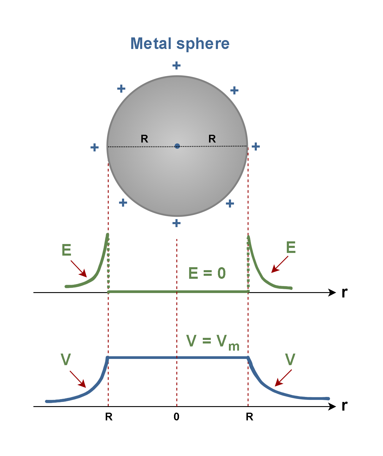
Figure 4 shows a metal sphere with a radius R that is positively charged. We can consider the magnitudes of the electric field E and the electric potential V inside and outside of its body.
Recall that for such charged bodies we can find E and V by Equation 4:

Where ‘r’ is the distance to the center of the sphere and ke = 8.9875 × 10⁹ (Nm2/C2) is the Coulomb’s constant. The units of E, V, and r are (N/C), (volts), and (meters), respectively.
Clearly, inside the conductor (r < R) the electric field is zero and the electric potential has its maximum value (Vm). On the surface of the sphere, both E and V have their maximum values, and by increasing the distance (r > R), both E and V decrease in terms of 1/r2 and 1/r respectively.
Capacitance
If the configuration of the uniform electric field in Figure 1 is reconstructed using two conducting plates, we typically design a capacitor. A capacitor is an electrical device consisting of two conductors separated by an insulating or dielectric medium. Capacitors, with different configurations, are used in a variety of electric and electronic circuits, such as tuning the frequency of radio receivers, eliminating sparking in automobile ignition systems or storing short-term energy for rapid release in electronic flash units.
Figure 5 shows a parallel-plate capacitor consisting of two flat metal sheets separated by distance d.
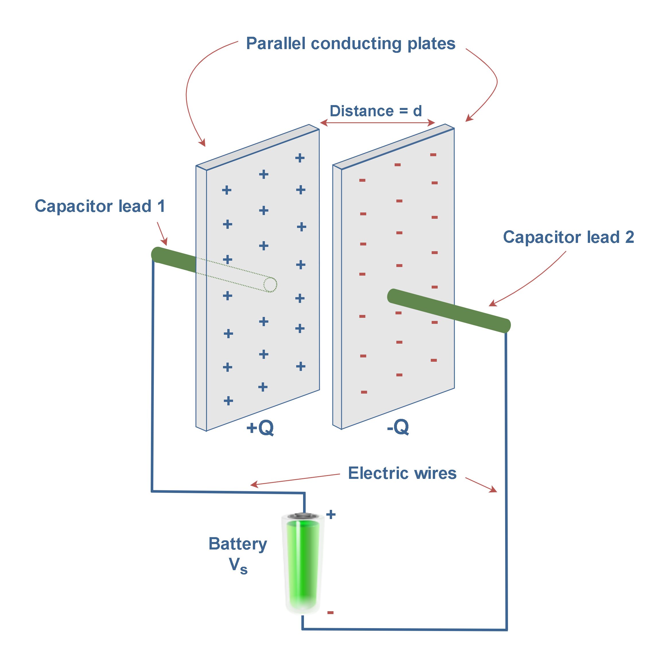
To transfer and hold charges on the plates and produce a uniform field structure, the plates are connected to the positive and negative terminals of a battery as a voltage source. The potential difference or the voltage drop between the positive and negative electrodes of the battery equals Vs. In this simple circuit, all the connections, including capacitor leads and wires, are made of conducting materials.
When the connections are made, electrons are pulled off one of the plates, leaving it with a charge of +Q, and are transferred through the battery to the other plate, leaving it with a charge of -Q, as shown in Figure 5. The transfer of charge stops when the potential difference across the plates equals the potential difference of the battery. Now, this charged capacitor is a device that stores energy, which can be reclaimed when needed for a specific application.
The capacitance C of a capacitor is defined as the ratio of the magnitude of the charge Q on either conductor (plate) to the magnitude of the potential difference ∆V between the conductors (plates), as explained in Equation 5:

The SI unit of capacitance is Farad (F), which is equal to Coulomb per volts (C/V). In other words, a capacitor that can store 1 Coulomb of charge with a potential difference of 1 Volt has a capacitance of 1 Farad. Since a capacitor of 1 Farad capacitance is much larger than what is ordinarily used in practice, microfarads (µF) and picofarads (pF) are commonly used units.
Potential Differences In Batteries
Batteries store energy in chemicals and use that energy via specific electrochemical reactions to distribute charges and create an electric field, similar to capacitors.
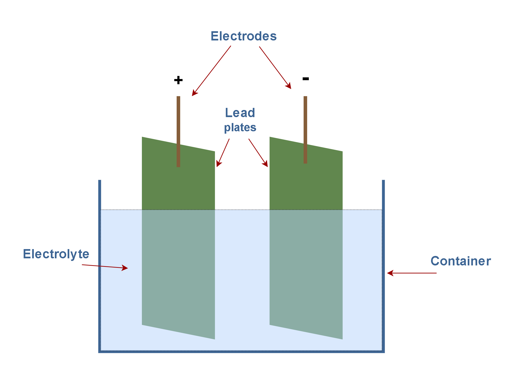
The traditional lead–acid battery is a type of rechargeable battery. Figure 6 shows the basic lead-acid cell which uses lead plates for the two electrodes, the positive and the negative ones. The container of the lead-acid battery can be made of glass. The electrolyte (sulfuric acid solution) creates a relatively uniform electric field between the electrodes when the battery is charged. The nominal voltage of a lead-acid cell (about 2.1V) represents the potential difference across this field.
A familiar application of potential difference is the 12-volt battery utilized in automobiles. These types of battery sets contain several lead-acid cells (each with about 2.1 V potential differences) in a serial structure. The battery provides the electrical current necessary to operate motors, headlights, radio sets, power windows, and so forth. Such a battery maintains a potential difference across its terminals, with the positive terminal +12 V higher in potential than the negative terminal. In practice, the negative terminal is usually connected to the metal body of the car, which can be considered to be at a potential of zero (virtual grounding).
Figure 7 shows a simple electric circuit containing a 12-volt battery as the source of electric energy, a lamp as the consuming device, and some connecting wires. Now consider a charge of +1 C, to be moved around the circuit that contains the battery connected to the lamp.
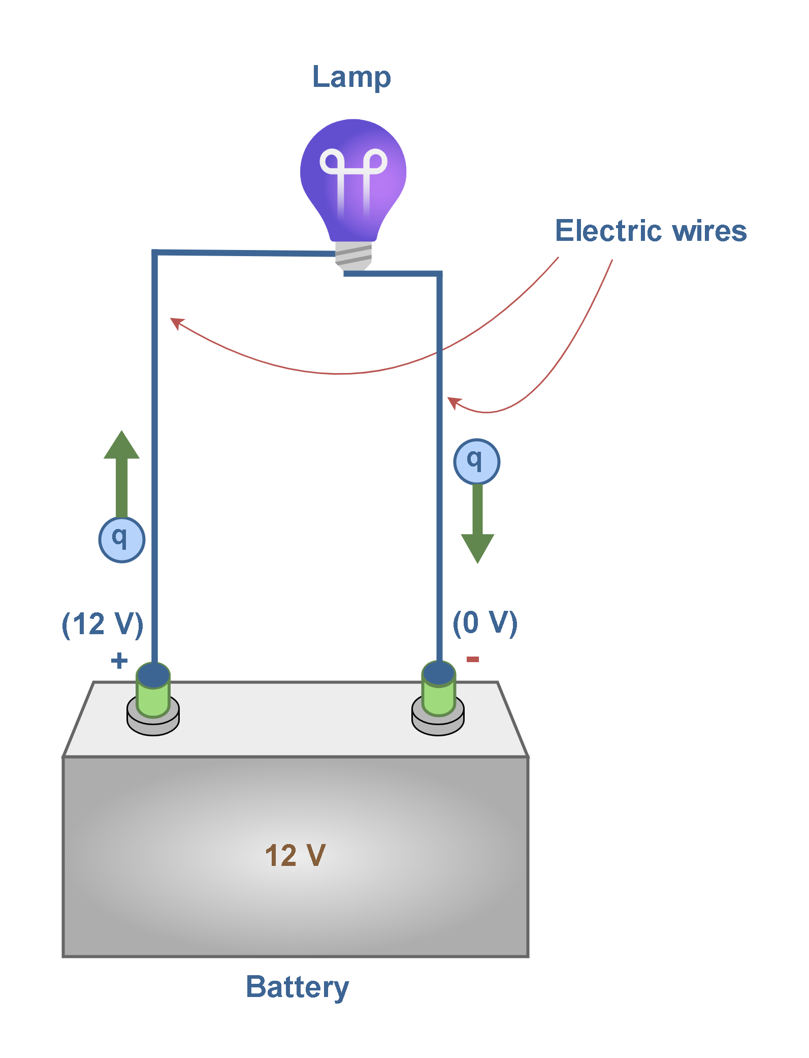
According to Equation 4, every coulomb of positive charge that leaves the positive terminal of the battery carries an energy of 12 J. As the charge moves through the external circuit toward the negative terminal, it gives up its 12 J of electrical energy to the external device. When the charge reaches the negative terminal, its electrical energy becomes zero. At this point, the battery takes over and restores 12 J of energy to the charge as it is moved from the negative to the positive terminal inside the battery, enabling it to make another transfer around the circuit.
Based on the mechanism of the battery operation, as the charge is moved inside the battery from the negative terminal (at 0 V) to the positive terminal (at 12 V), the work done on the charge by the battery is 12 J.
Conclusions
Understanding the electric potential is crucial for solving many practical problems in electromagnetism, such as those involving parallel plate capacitors or the behavior of charges in uniform fields. It also helps describe how charges interact within electric fields and how energy is stored and transferred in electrical systems.
Summary
If an electric field has the same direction everywhere in a particular space, it is said to be uniform.
- In a uniform field, the field lines are parallel.
- The amount of work per unit charge is equal to the force per unit charge (or field intensity E) times the distance through which the charge is moved.
- The electric potential difference is the work per unit charge that would have to be done by some electric force to move a charge from point A to point B in a uniform electric field.
- Electric potential is a scalar quantity.
- Voltage is another term for electric potential, it measures the difference in electric potential between two points.
- The SI unit of electric potential is the joule per coulomb (J/C), called the volt (V).
- A surface on which all points are at the same potential is called an equipotential surface.
- Equipotential surfaces are always perpendicular to electric field lines.
- When a particle moves from one point to another point on an equipotential surface, the net electric force does not work and ΔV equals zero there.
- The charges on a conductor are assumed to be in equilibrium with each other, so none are moving.
- the electric field just outside the surface of a charged conductor in electrostatic equilibrium is perpendicular to the surface and the field inside the conductor is zero.
- All points on the surface of a charged conductor in electrostatic equilibrium are at the same potential.
- A simple capacitor consists of two parallel metal plates separated by a distance d.
- A lead-acid battery uses 2 lead plates (connected to the positive and the negative terminals) inside an electrolyte for the conversion of chemical energy into electrical power.
Please follow and like us:
More tutorials in Electromagnetism
Subscribe
Login
0 Comments


