

BCD Counter Circuit
- Muhammad Shahid
- m_shahid@live.co.uk
- 15 min
- 181 Views
- 0 Comments
- 2 Likes

BCD Counter Circuit
A special digital counter called a BCD counter may count up to ten when a clock signal is supplied.
As previously demonstrated, toggle T-type flip flops may function as separate divide-by-two counters. By joining many toggle flip-flops in a series chain, we may create a digital BCD counter that counts or shows the occurrences of a certain count sequence.
The output of one counting stage serves as the clock pulse for the subsequent stage in asynchronous counters, and clocked T-type flip-flops function as a binary divide-by-two counter. Then, a flip-flop counter has two alternative output states. A divide-by-2N counter may be created by adding more flip-flop stages. However, the fact that 4-bit binary counters only count from 0000 (0) to 1111 (15) is a disadvantage.
We need to have a counter that can count just the binary numbers 0000 to 1001 to create a digital counter that counts from 1 to 10. That is, in decimal, from 0 to 9. Fortunately for us, counting circuits are easily found as integrated circuits; the Asynchronous 74LS90 Decade Counter is one such circuit.
When a clock signal is applied, digital counters count upward from zero to a predefined count value. After the count value is reached, resetting them restarts the counter from zero. A decade counter starts at 0 and counts to 9, then reset to zero after nine counts. It is mandatory to mention that the counter needs at least four flip-flops in its chain to represent each decimal digit to count to a binary value of nine.
BCD Counter State Diagram
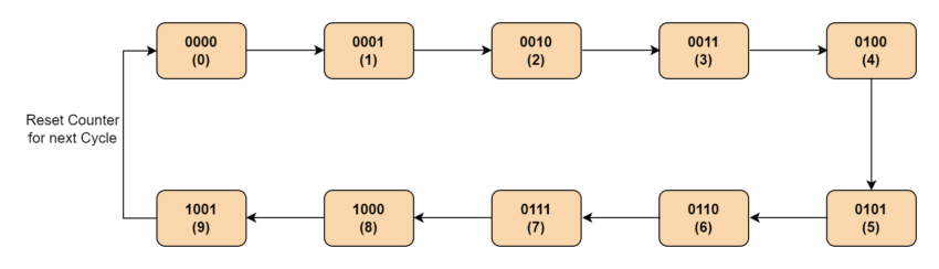
Subsequently, a decade counter has four flip-flops and sixteen possible states, out of which only ten are utilized. By connecting many counters, we might count to 100, 1000 or any other desired ultimate count number.
A counter’s modulus is the total number of counts it is capable of counting. A modulo-n counter is a counter that resets to zero after n counts. Examples of modulo-n counters include modulo-8 (MOD-8), modulo-16 (MOD-16), and so on. On the other hand, a “n-bit counter” has a count range of 0 to 2n-1.
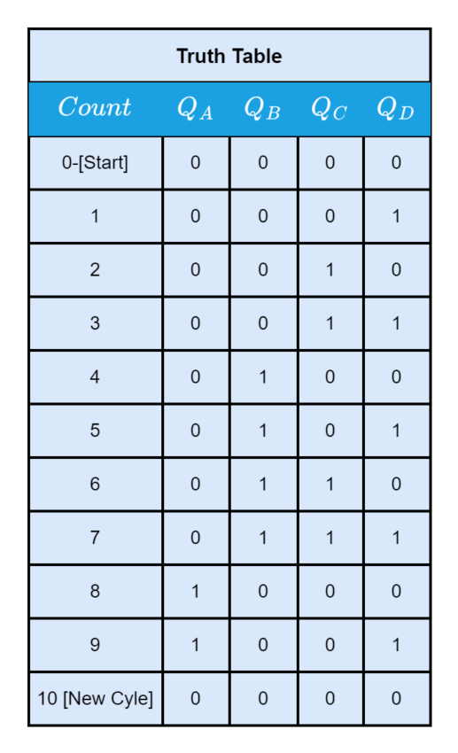
However, a counter that resets after ten counts with a divide-by-10 count sequence from binary 0000 (decimal “0”) through to 1001 (decimal “9”) is known as a “binary-coded-decimal counter,” or BCD Counter for short. A MOD-10 counter can be built with a minimum of four toggle flip-flops. This was demonstrated in the Asynchronous Counters tutorial.
It is termed a BCD counter because, in contrast to a straight binary counter, its 10-state sequence is that of a BCD code and lacks a regular pattern. Then, a single-stage BCD counter, like the 74LS90, may count to nine pulses maximum since it counts from decimal 0 to decimal 9. Furthermore, take note of the fact that a digital counter may function as a bidirectional counter, counting both up and down in response to an input control signal.
The 8421 binary-coded decimal code consists of four binary digits. The binary weight of the four utilized digits or bits is indicated by the notation 8421. 23 = 8, 22 = 4, 21 = 2, and 20 = 1, for instance. The primary benefit of BCD coding is its ease of translation between binary and decimal representations of numbers.
The 74LS90 BCD Counter
In simple terms, the 74LS90 integrated circuit generates a BCD output code by acting as a MOD-10 decade counter. An internal connection between four master-slave JK flip-flops allows the 74LS90 to function as both a MOD-2 (count-to-2) and a MOD-5 (count-to-5) counter. The 74LS90 features three toggle JK flip-flops that create an asynchronous counter driven by the CLK B input, as well as one independent toggle JK flip-flop powered by the CLK A input.
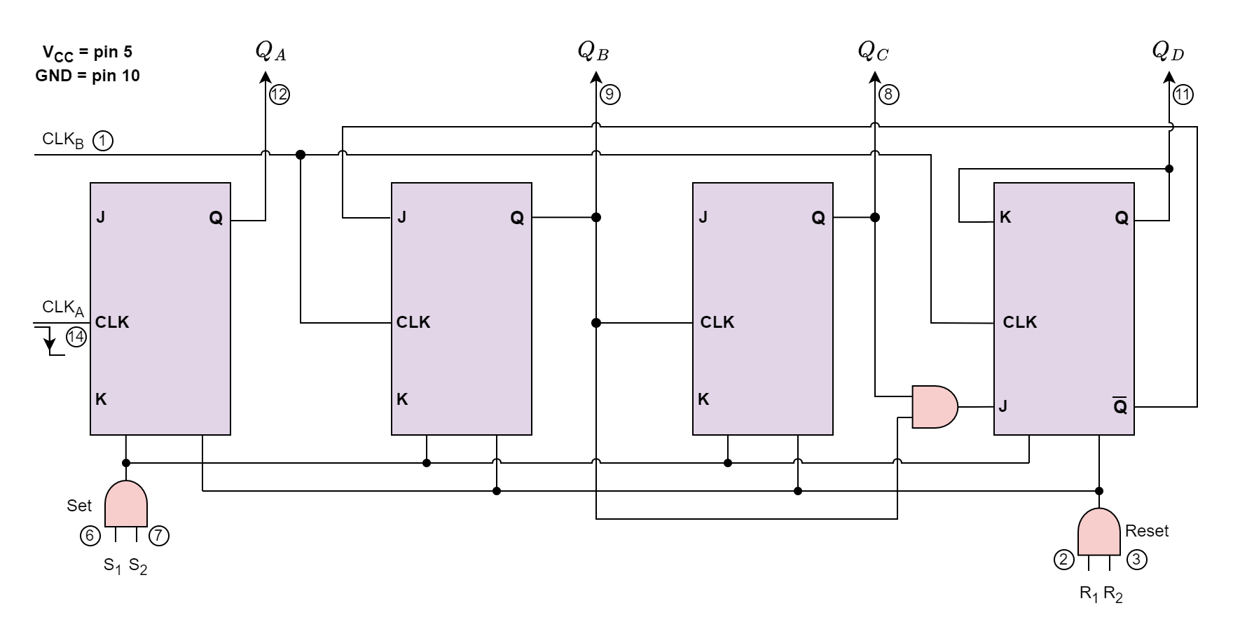
The letter Q, followed by a numeric subscript that represents the binary weight of the relevant bit in the BCD counter circuits coding, designates the counters’ four outputs. Thus, take QA, QB, QC, and QD as examples. The clock signal’s negative going edge, or when the clock signal CLK changes from logic 1 (HIGH) to logic 0 (LOW), initiates the 74LS90 counting sequence.
Pins S1 and S2 are “set” input pins, while the extra pins R1 and R2 are counter “reset” pins. When the Set inputs S1 and S2 are linked to logic 1, they set the counter to the maximum, or 9 (1001), regardless of the current count number or position. Similarly, the Reset inputs R1 and R2 reset the counter back to zero, 0 (0000).
As previously stated, the 74LS90 counter is comprised of a divide-by-2 counter and a divide-by-5 counter that are both included in the same package. Subsequently, we may utilize either counter to generate a divide-by-2 frequency counter only, a divide-by-5 frequency counter exclusively, or combine the two to generate our preferred divide-by-10 BCD counter.
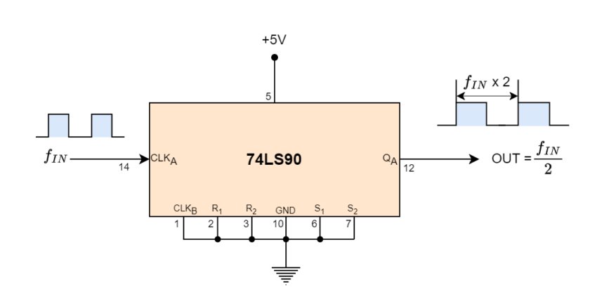
By disabling the four flip-flops that comprise the divide-by-5 counter section, we may generate a conventional divide-by-2 binary counter suitable for frequency division circuits by applying a clock signal to pin 14 (CLKA) and extracting the output from pin 12 (QA).
74LS90 Divide-by-2 Counter
We may deactivate the first flip-flop above and apply the clock input signal straight to pin 1 (CLKB), taking the output signal from pin 11 (QD), as illustrated, to create a typical divide-by-5 counter.
74LS90 Divide-by-5 Counter
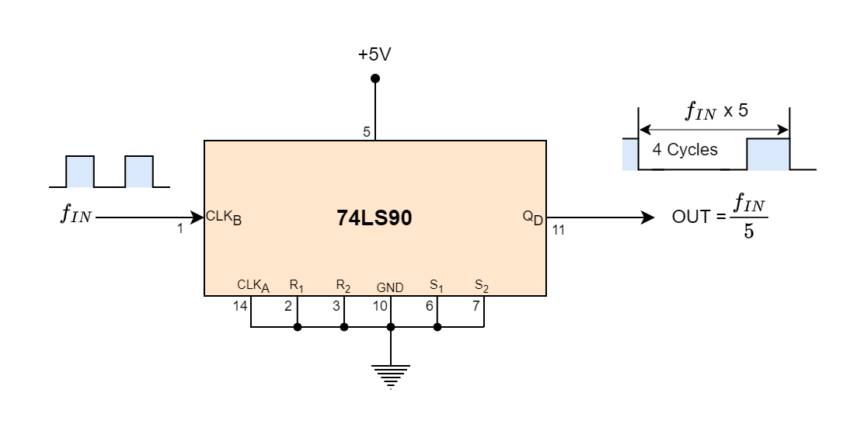
It should be noted that the output waveform of this divide-by-5 counter design has a 4:1 mark-space ratio rather than being symmetrical. In other words, a LOW or logic “0” output is produced by four input clock signals, while a HIGH or logic “1” output is produced by the fifth input clock signal.
Using both internal counter circuits results in a divide-by-10 BCD decade counter with a 2 times 5 divide-by value. The first output QA from flip-flop “A” may be linked to the CLKB input as illustrated to expand the counter and create a 4-bit BCD counter, as it is not intrinsically coupled to the subsequent stages.
74LS90 Divide-by-10 Counter
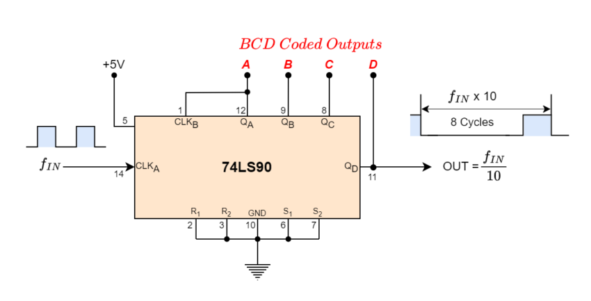
The ability of BCD counters to clear all their flip-flops after the ninth count allows us to see that they are binary counters that count from 0000 to 1001 before resetting. A pushbutton switch (SW1) connected to clock input CLKA will cause the counter to increment by one each time the pushbutton switch is released. We could see the binary-coded decimal count as it happened if we connected light-emitting diodes (LEDs) to the output terminals, QA, QB, QC, and QD as shown.
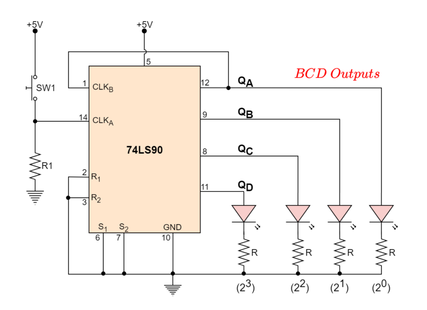
When the push-button switch, SW1, is used repeatedly, the count will rise to nine, 1001. The outputs ABCD will reset back to zero to begin a fresh count sequence after the tenth transmission. It is possible to utilize the decade counter to drive a digital display with such a MOD-10 round number of pulses.
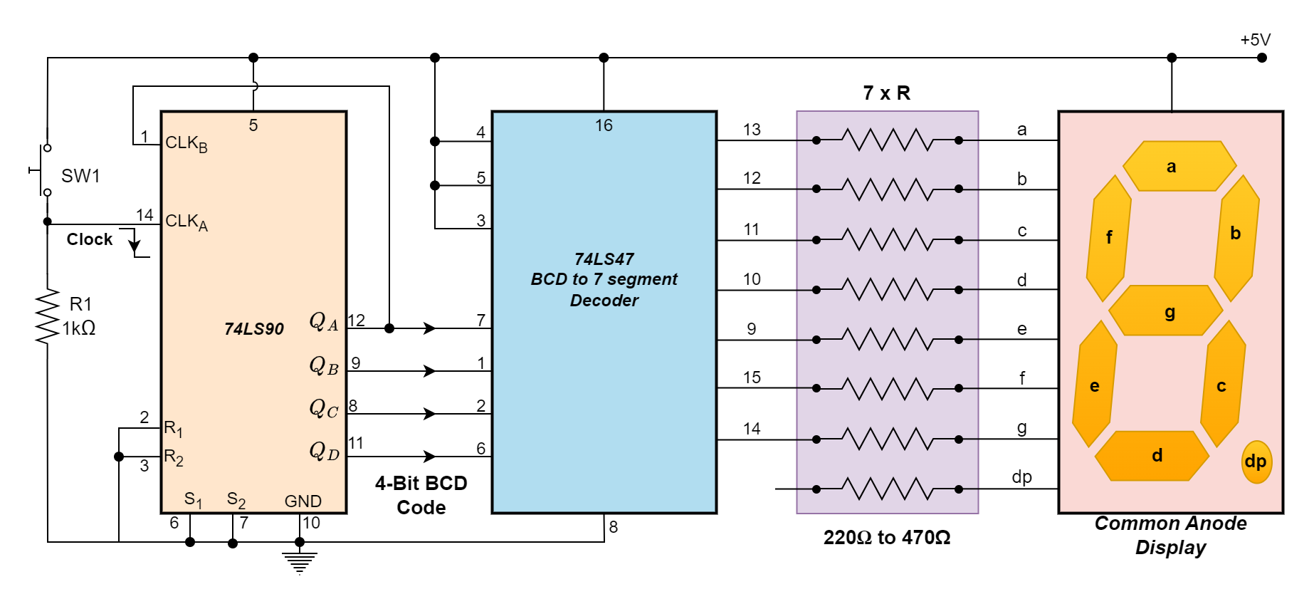
The BCD output must first be correctly decoded for us to display the count sequence on a seven-segment display. A Decoder is a digital circuit that can decode the four outputs of our 74LS90 BCD counter and illuminate the necessary display segments.
Driving a Display
A BCD to 7-segment Display Decoder IC, i.e. 74LS47, has previously been developed and manufactured to accomplish that, precisely. The BCD digits A, B, C, and D have four inputs on the 74LS47, and outputs for each segment of the seven-segment display.
One input connection for each LED segment and one that serves as a common terminal or connection for all internal display segments are typically found on a basic 7-segment LED display. Additionally, some displays include a decimal point (DP) option.
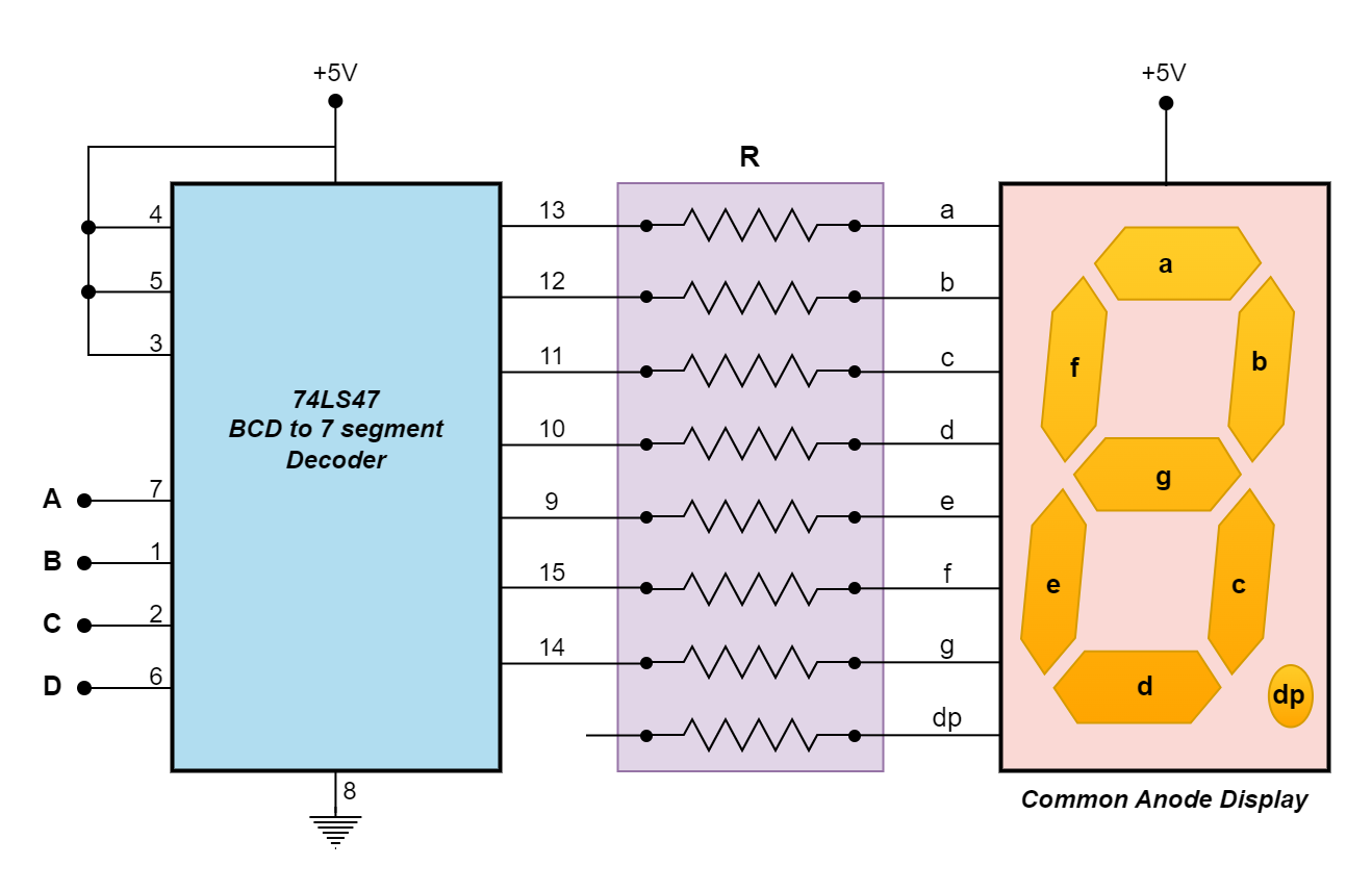
After receiving the BCD code, the 74LS47 display decoder produces the signals required to turn on the relevant LED segments that show the number of pulses applied. Since the 74LS47 decoder is intended to power a common-anode display, an LED segment can be turned “OFF” with a HIGH (logic-1) output and illuminated with a LOW (logic-0) output. The (Blanking Input/Ripple Blanking Output), (Ripple Blanking Input), and (Lamp test) all need to be open or connected to logic-1 (HIGH) for the system to function normally.
It should be noted that the 74LS48 decoder/driver IC is identical to the 74LS47 in that it has active HIGH outputs intended to decode a common cathode 7-segment display, whereas the 74LS47 has active LOW outputs and is intended to decode a common anode 7-segment LED display. Therefore, a 74LS47 or 74LS48 decoder IC may be required, depending on the kind of 7-segment LED display you have.
The 74LS90 BCD Counter’s corresponding outputs may be linked to the binary coded decimal inputs of the 74LS47 to enable the 7-segment display to show the count sequence each time the push button SW1 is pressed. The count on activation or release of the push button switch, SW1, may be modified by adjusting the push button’s location and the 1kΩ resistor.
It should be noted that a 7-segment display is composed of seven separate light-emitting diodes. It is advisable to use a current limiting resistor in series with each of the seven LEDs as illustrated to limit the current flowing through a seven-section display. However, there are two ways we might go about doing this.
Current Limiting Resistors
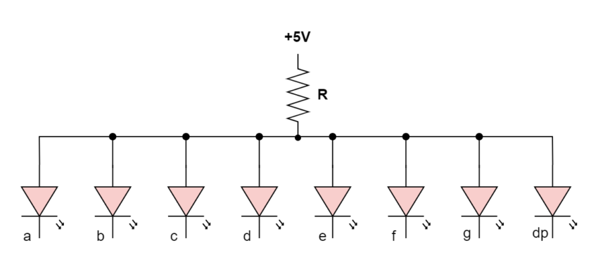
Single Resistor: As shown in the figure, R is utilized in this instance as a single-series current-limiting resistor. This is the most straightforward way to use the 7-segment display if maintaining a consistent brightness level is not a major priority for you.
An LED’s light output is proportional to the current passing through it; the current passing through the resistor is divided among the display segments. The number of segments that are lit simultaneously now determines the display’s brightness.
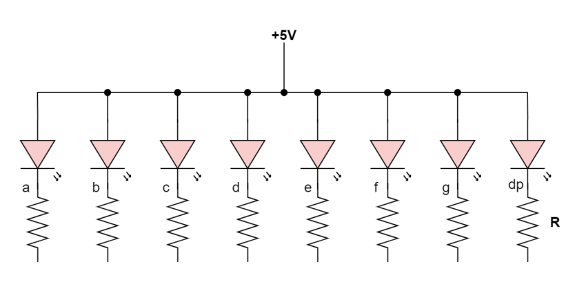
Multiple Resistors: As shown in the above simple BCD counter circuit, each segment has a separate current-limiting resistor in this case.
Since 7-segment displays typically need between 12 and 20 milliamperes to illuminate the segments, the resistance value of the current limiting resistor—all of which will be the same—is selected to keep the current within these ranges. Be aware that if a display is operated at 40mA or more, it may be damaged.
The benefit of this is that the display has a consistent brightness since the brightness of any one LED segment is independent of the condition of the other six LEDs. Since the needed LED intensity is also determined by the quantity of ambient light, the values of the current limiting resistors may be selected to produce the appropriate level of brightness.
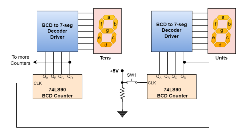
Our design uses a 74LS90 BCD Counter and a 74LS47 7-segment display driver to display basic 0 to 9 digital counters. We would need to cascade two different divide-by-ten counters together to count over 10 and get a 2-digit base-ten counter and display. A two-digit BCD counter would reset to 00 after counting in decimal from 00 to 99 (0000 0000 to 1001 1001). It should be noted that although this code will result in a 2-digit counter, values representing Hexadecimal integers from A to F are invalid.
Similarly, three cascaded decade counters are needed if we wish to count from 0 to 999 (0000 0000 0000 to 1001 1001 1001). As demonstrated, one may create numerous decade counters by simply building one BCD counter circuit for each decade.
2-digit BCD Counter from 00 to 99
BCD Counter Summary
- A BCD (Binary-Coded Decimal) counter is a type of digital counter that counts from 0 to 9, using a series of toggle T-type flip-flops to create a divide-by-10 sequence. It resets after reaching 9, unlike a standard binary counter that counts from 0 to 15 in a 4-bit configuration.
- An integrated circuit that functions as a MOD-10 BCD counter is called the 74LS90. Divide-by-2 and divide-by-5 counters are mixed and can be used separately or in combination to produce the necessary counting sequence. After counting from 0 to 9, it returns to 0. An n-bit binary counter is composed of “n” flip-flops, which count from 0 to (2n-1). Binary counters are counters that operate using a binary sequence.
- The 74LS47 is an example of a BCD to a 7-segment decoder that is used to show the BCD output on a seven-segment display. The BCD output is decoded by the 74LS47, which then lights the relevant display segments to reveal the matching decimal digit.
- The 74LS90 has multiple pins for clock inputs and for setting and resetting the counter. A working BCD counter circuit that shows the count sequence may be made by connecting the right pins and adding extra parts like resistors and LEDs.
- To count beyond nine, several BCD counters can be cascaded. For example, two counters can be used for a two-digit decimal display (00 to 99) or three counters for a three-digit display (000 to 999). The count capacity is increased by one decimal point for each extra counter.
Please follow and like us:
Subscribe
Login
0 Comments


