Bidirectional Counters
- Muhammad Shahid
- m_shahid@live.co.uk
- 10 min
- 212 Views
- 0 Comments
- 5 Likes

Introduction
A bidirectional counter is a binary counter that operates synchronously in both up and down directions. It is capable of counting both toward & away from a predefined number and back to zero. Any given count sequence can be counted by such bidirectional counter in either the up or down direction.
It is occasionally required to count “down” from a predefined value to zero and count “up” from zero and grow or increment to some preset number. This allows us to create an output that activates when the zero count or any other pre-set value is reached.
When an external clock pulse is applied to a binary or Binary Coded Decimal (BCD) down counter, the count drops by one from a predetermined number. Typically, this counter is called a Down Counter (CTD). Special dual-purpose integrated circuits (ICs) with an additional input pin to select the up- or down-count mode are 4-bit binary up- or down-counters, such as the TTL 74LS193 or CMOS CD4510.
Design of Bidirectional Counters
Flip-flops, which store the count, and extra logic circuits that regulate the counting’s direction are the fundamental parts of a bidirectional counter. When designing a bidirectional counter, the right flip-flops and logic gates must be chosen, and a circuit that appropriately processes the U/D control signal to regulate the counting direction must be created. The counting range (modulus), counter type (synchronous or asynchronous), and counting sequence (binary or decade) must first be defined. Second, choose the flip-flops (D, JK, etc.) according to the kind of counter required. Then, create the necessary flip-flop inputs by designing the combinational logic circuit to process the U/D control signal. Make sure the design is validated and that the counting behavior is correct in both directions by using simulation tools.
Advanced bidirectional counter designs provide extra features including cascade capabilities, configurable counting ranges, and preset and clear functionality for complicated applications. The counting range can be increased by cascading numerous counters. For example, an 8-bit counter that can count from 0 to 255 is produced by cascading two 4-bit counters. For adaptive systems that require real-time adjustments, programmable counters allow for the dynamic modification of the counting range and direction based on external inputs. While clean functionality resets the number to zero, preset functionality allows the counter to be set to a specified value. These characteristics improve flexibility and control.
4-bit Count Down Counter
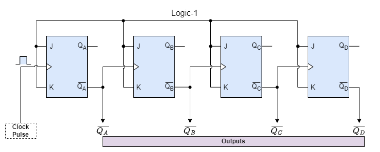
As shown in the figure, instead of being activated by the Q output as in the up-counter configuration, the 4-bit counter uses the Q̅ output of the preceding flip-flop to trigger the state change of each flip-flop on the falling edge (1-to-0 transition) of the CLK input. Consequently, rather than moving from 1 to 0, each flip-flop will change states when the one before it goes from 0 to 1 at its output.
Bidirectional Counter
While both synchronous and asynchronous counters can count “Up” or “Down,” bidirectional counters are a more “universal” kind of counter that can count in both ways, Up or Down, depending on the condition of its input control pin. Bidirectional counters, also referred to as Up/Down counters, may count in either way throughout any given count sequence. As seen below, they can be reversed at any time by applying an extra control input.
Synchronous 3-bit Up/Down Counter
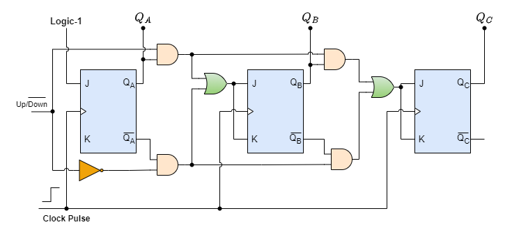
The circuit shown above is a typical three-bit synchronous counter that counts from zero (000) to seven (111) and back to zero using JK flip-flops that are set to function as toggle or T-type flip-flops. The 3-bit counter then proceeds in one of two ways: either upward (0,1,2,3,4,5,6,7) or downward (7,6,5,4,3,2,1,0).
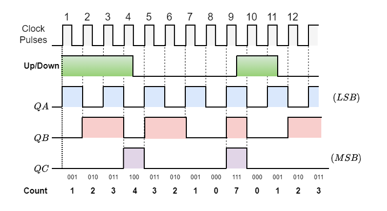
Most bidirectional counters are often configured to flip their count direction up or down at any time throughout their counting cycle. This is accomplished by employing a second input pin that controls the count direction (up or down). The timing diagram illustrates how the counter functions when the state of this Up/Down input changes.
Nowadays, a complete bidirectional counter chip consists of an Integrated Circuit (IC) that has both up and down counters integrated into it. This IC may be completely programmed to count in both directions from any preset number. The “74F569” is a completely synchronous Up/Down binary counter, the 74HC190 4-bit a BCD decade Up/Down counter, and the CMOS 4029 4-bit Synchronous Up/Down counter are common devices.
Applications of Bidirectional Counters
These counters can count events or readings that are subject to bidirectional fluctuations in telemetry systems. For example, Monitoring and adjusting levels in a water reservoir.
They are used in systems for controlling and timing the length of traffic signals. Changing the length of the green and red lights by traffic flow is one example.
They are employed for accurate angular position control and measurement in motor shafts and other rotating machinery. For instance, they are used to provide feedback on the precise location of the motor shaft in servo motors.
In Computer Numerical Control (CNC) machines and robots, they are essential to monitor the location of moving components. Like, tracking the position of a robotic arm in an industrial robot.
Bidirectional counters are used to count time in two modes: reducing for countdowns and growing for elapsed time. An example would be a microwave oven’s countdown timer.
Advantages of Bidirectional Counters
Bidirectional counters are more useful for a wider range of applications than basic (unidirectional) counters because they offer various benefits. For example:
- Scenarios requiring both increment and decrement operations without the requirement for separate devices for each function is one of the main advantages.
- Separate up and down counters use more space on a circuit board than a single bidirectional counter.
- Up and down counting can be combined into a single device, which lowers the system’s overall cost and makes the system more attractive from an economic standpoint.
- Bidirectional counters improve accuracy and reaction times by giving instantaneous data on direction changes in control systems like motor controllers or robotic arms.
- Ideal for intricate jobs including reversible procedures, dynamically adjusting systems, and location tracking.
Conclusion
- A bidirectional counter is a binary counter that can count both up and down, moving towards or away from a predefined number and back to zero.
- These counters can handle any given count sequence in either direction (up or down) and are capable of activating outputs when zero or any preset value is reached.
- Bidirectional counters can be configured as either synchronous or asynchronous and typically include a control pin for switching between up and down counting modes. Examples include the TTL 74LS193 and CMOS CD4510.
- Widely used in applications such as telemetry systems, traffic signal control, angular position measurement in motors, CNC machines, and countdown timers in devices like microwave ovens.
- These counters offer versatility by combining up and down counting in one device, reducing space and cost while enhancing accuracy and responsiveness in control systems. They are ideal for reversible processes and dynamic adjustments in various systems.
Please follow and like us:
Subscribe
Login
0 Comments