Electric Conductivity, Resistance and Ohm’s Law
- Kamran Jalilinia
- kamran.jalilinia@gmail.com
- 15 min
- 2 Views
- 0 Comments
Introduction
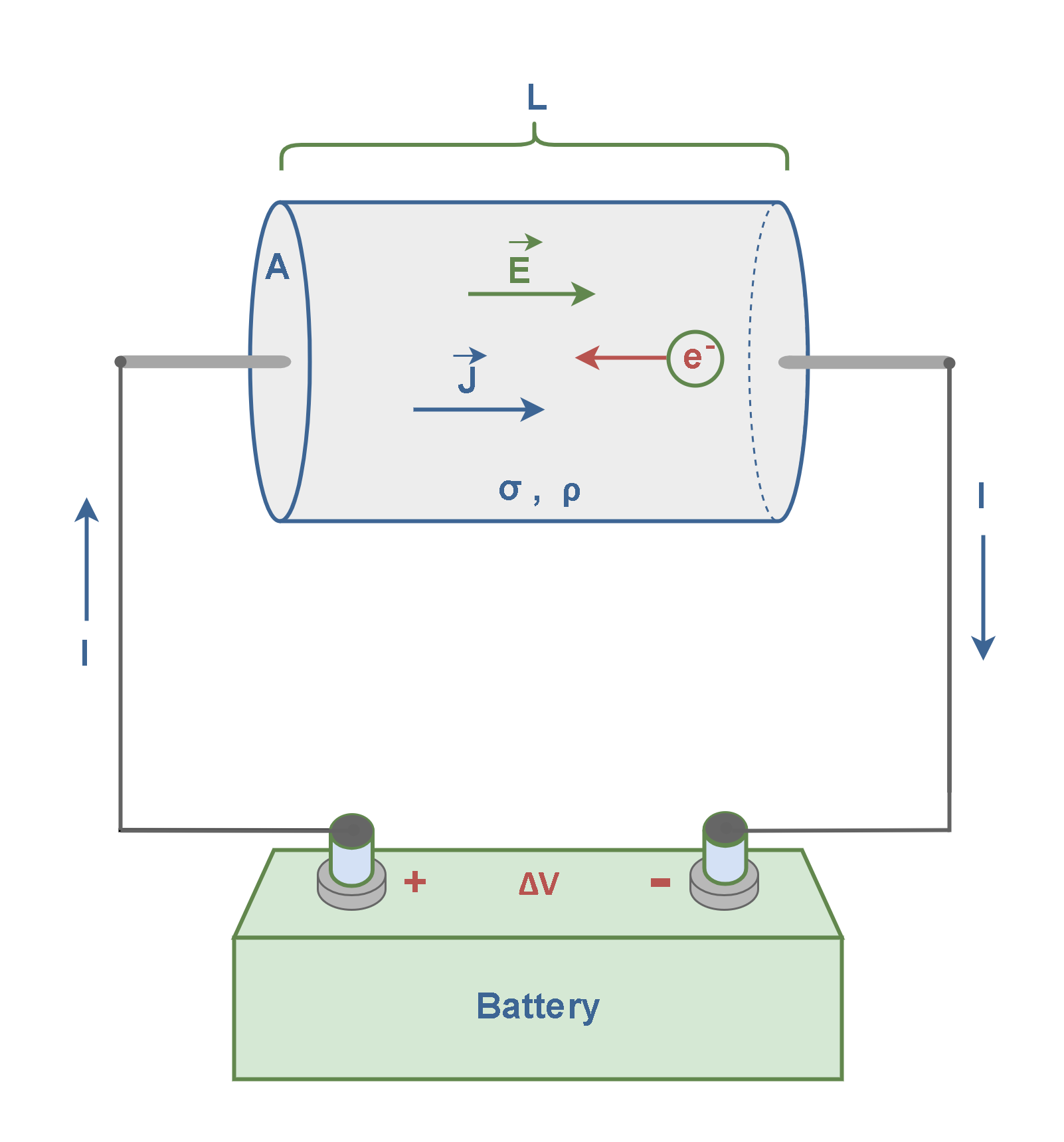
Consider a piece conductor in the shape of a cylinder with a voltage applied across its ends, as depicted in Figure 1.
When a potential difference (voltage ∆V) is applied between two points in a conductor, an electric field E is created, and free electrons (e–) in the conductor feel a force due to the electric field. This phenomenon causes free charges to move and produce an electric current. The wires must be part of a closed circuit for a steady current ‘I’ to flow in wires in this simple circuit. The electric current in the wires is proportional to the drift velocity of the free electrons inside the conductor.
Conductivity is one of the primary constitutive parameters that is commonly used to characterize the electromagnetic properties of materials. The key idea is that conductivity is a property of materials that determines conduction current density (J) in response to an applied electric field.
This experimental relationship was first summarized by the German physicist Georg Simon Ohm in 1827. Equation 1, known as Ohm’s Law for Electromagnetics, states that the volume density of current equals conductivity times the electric field intensity:

where E is the electric field intensity (V/m); J is the current density vector describing the current flow, having units of Ampere/m2; and ‘σ’ is conductivity.
In this formula, σ has units of mhos per meter (Ω-1m-1). The mho (the inverse of the resistance unit ohm 1 Ω-1) was the old term for electrical conductance and it is still used. A new name for this unit was adopted in 1971, honoring Ernst Werner von Siemens (1816 – 1892) who was a German electrical engineer, inventor, and industrialist. Then, σ is more commonly expressed as Siemens per meter or S/m.
The concept explained in Equation 1 provides a macroscopic point of view on conductivity, which is essentially a measure of a material’s ability to allow the flow of electric current. It is important to note that the current being addressed here is the conduction current and not any other form of current.
Conductors And Insulators
The conductivity (σ), as an electromagnetic property, depends on both the availability and mobility of true charges within the material. Materials in terms of their conductivity σ can be classified in some categories. Here are a few classes of materials that are frequently encountered:
- Perfect insulators; a perfect vacuum or free space contains no charge (in the absence of material) and therefore it is a perfect insulator with σ = 0.
- Good insulators; typically have conductivities σ << 10-10 S/m, which is sufficiently low that the resulting currents can usually be ignored. The most familiar example is air, which has a conductivity only slightly greater than that of free space. An important class of good insulators is lossless dielectrics, which are well-characterized in terms of relative permittivity (ϵr) alone, and for which σ = 0 may usually be assumed.
- Poor insulators; have low conductivities, however, the resulting currents cannot be ignored. These lossy dielectrics are well-characterized in terms of ϵr and σ.
- Semiconductors; are materials mostly used in transistors and integrated circuits and have intermediate conductivities, typically about 10+1 S/m. Although the type of current in semiconductors is a conduction current, its behavior and the mechanisms behind it differ significantly from those in metals.
- Good conductors; are materials with very high conductivities, typically greater than 105 S/m. A good conductor is a material that contains a supply of charges (electrons) that can move freely within the material. When an electric field is applied to a good conductor, charges move in the direction determined by the electric field, creating current flow in that direction. An important category of good conductors includes metals, with certain metals including alloys of aluminum, copper, silver, and gold reaching conductivities on the order of 107 S/m. There is no significant storage of energy in such materials, so the concept of relative permittivity (ϵr) is not relevant for good conductors. They are often used in wiring and electrical components.
- Perfect conductors; are materials in which σ → ∞, E → 0. Metals are often modeled as perfectly conducting equipotential volumes to simplify analysis.
In the above-mentioned classification, at the two extremes, we have perfect insulators, for which σ = 0, and perfect conductors, for which σ → ∞. Some special materials approach these extremes, whereas most of the others fall midway between these conditions.
The conductivity values of some common materials for the temperature of 20 ֯C are listed in Table 1.
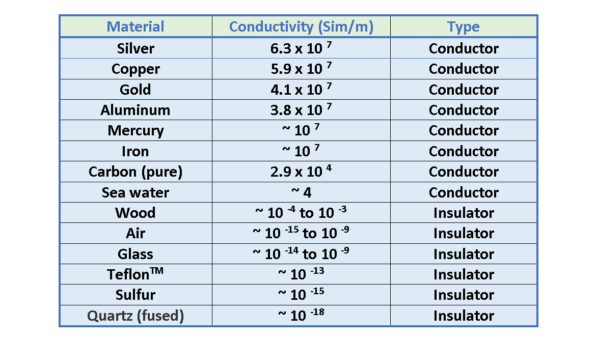
Figure 2(a) shows a test structure based on a simple circuit containing a battery, some wires, and two electrodes. If we put a piece of a conductive material (like a metal bar) between the 2 positive and negative electrodes, because of the potential difference and electrons’ movement, an electric current ‘I’ will be flowing in all the circuits. The amount of the current depends on the voltage ∆V and conductivity of the material under test.
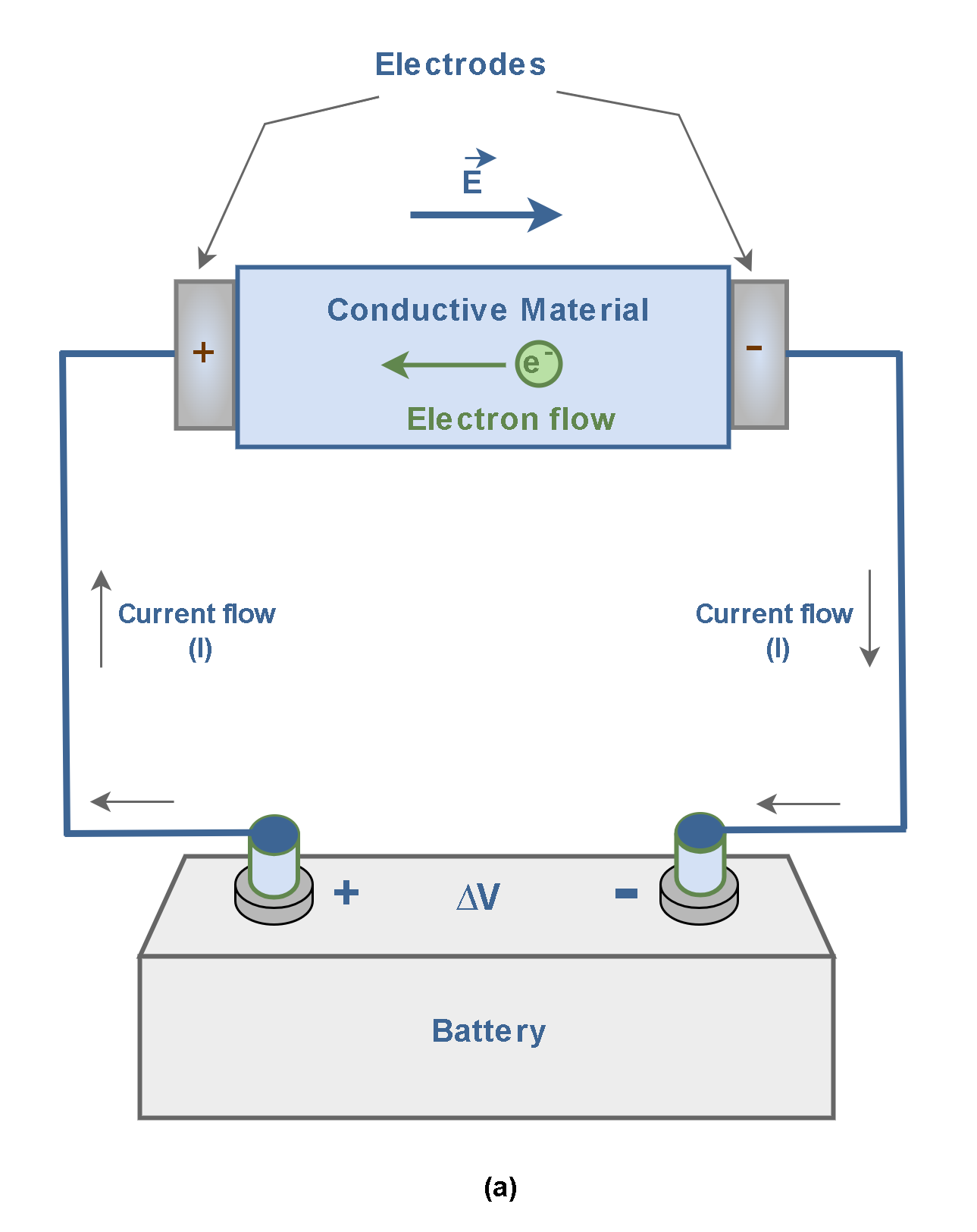
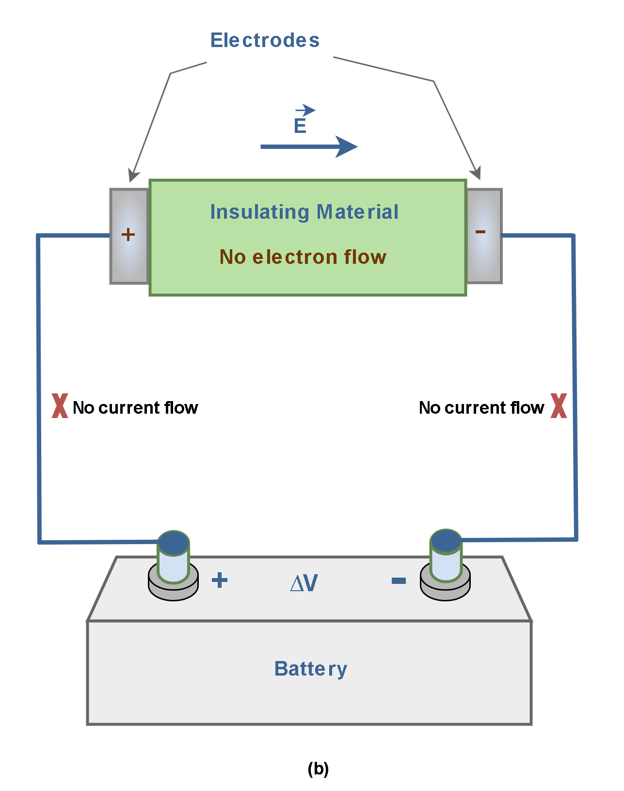
Figure 2(b) shows the same structure but with a piece of a non-conductive material (like a wooden rod) between the 2 positive and negative electrodes. Here, although there is the potential difference and the electric field, there is no movement of free electrons. Then, the electric current won’t be flowing in the circuit. Because the atomic structure of the insulator does not allow free electrons to move.
Electric Resistivity
We have already considered the concept of drift velocity from a microscopic viewpoint in the previous article. Inside the conducting body, an electron gains speed as the electric force associated with the internal electric field (E) accelerates it, giving it a velocity in the direction opposite that of the electric field.
Essentially, free electrons carrying the current don’t move in straight-line paths through the conductor. Instead, they undergo repeated collisions with the metal atoms. A collision with an atom randomizes the electron’s velocity, reducing it in the direction opposite the field. The process then repeats itself. The effect of these collisions on electrons is similar to the force of internal friction in mechanical systems. It causes a reduction in the speed of free electrons’ movement to the destination. This phenomenon is the origin of a material’s electric resistivity.
Resistivity is essentially a fundamental property of a material that quantifies how strongly it resists the flow of electric current. Resistivity is an intrinsic property of a material and does not depend on its size or shape. Every material has a characteristic resistivity that depends on its electronic structure and temperature.
Resistivity is indicated by ‘ρ’ and it is measured in units of Ohm-meters (Ω.m). Good electric conductors have very low resistivity, and good insulators have very high resistivity. Table 2 lists the resistivity of various materials at 20 °C.
Different materials have vastly different conductivity and resistivity values:
- Conductors like copper have high conductivity (low resistivity)
- Insulators like wood have very low conductivity (high resistivity)
Therefore, the mathematical relationship between conductivity and resistivity is explained in Equation 2:

This means they are reciprocals of each other. While this mathematical relationship suggests a perfect reciprocal relationship, in real-world measurements, this reciprocity isn’t always straightforward or exact. For example, metals typically follow the reciprocal relationship more closely, while semiconductors and complex materials can show significant deviations.
Essentially, there are some factors influencing conductivity and resistivity in different materials; like, atomic or molecular structure, and temperature variations.
In scientific and engineering applications, researchers often use practical measurements rather than relying solely on the theoretical 1/ρ relationship. This means carefully measuring both conductivity and resistivity under specific conditions to understand the material’s true electrical behavior.
Temperature Dependence Of Electrical Resistivity
For most metals, resistivity increases with increasing temperature. This correlation can be understood as follows: as the temperature of the material increases, its constituent atoms vibrate with greater amplitudes. As a result, the electrons find it more difficult to get by those atoms, just as it is more difficult to pass through a crowded room when people are in motion than when they are standing still. So, the increased electron scattering with increasing temperature results in increased resistivity.
Over a limited temperature range, the resistivity of most metals increases with increasing temperature according to Equation 3:

where ‘ρ’ is the resistivity at some temperature T (in Celsius degrees), ‘ρ0’ is the resistivity at some reference temperature ‘T0’ (usually taken to be 20°C), and ‘α’ is a parameter called the temperature coefficient of resistivity. Temperature coefficients for various materials are also provided in Table 2.
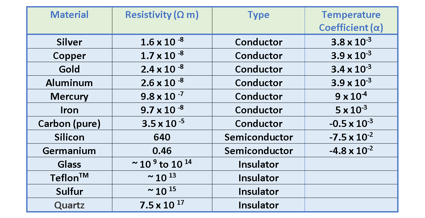
Table 2 shows that: for most metals, resistivity increases with temperature, while for semiconductors, it decreases.
Electric Resistance
Resistance is also a measure of how much an object opposes the flow of electric current when a voltage is applied across it. Resistance depends on the resistivity ρ, which is a natural characteristic of the material, and dimensions of the object.
We can refer again to Figure 1 to consider the resistance of that cylindrical piece of conductor. Firstly, the resistance of a conductor increases with length, which makes sense because the electrons going through it must undergo more collisions in a longer conductor. Secondly, a smaller cross-sectional area also increases the resistance of a conductor, just as a smaller pipe slows the fluid moving through it. The resistance, then, is proportional to the conductor’s length ‘L’, and inversely proportional to its cross-sectional area ‘A’. Equation 4 defines the resistance R of a conductor based on these relationships:

where the constant of proportionality, ρ, is called the resistivity of the material in units of Ohm-meters (Ω.m). The dimensions of L and A are meters (m) and squared meters (m2) respectively. Resistance values are measured in Ohms (Ω).
Resistance is also a property of most practical electronic devices as well, whether it is desired or not. For many materials, including most metals, experiments show that the resistance remains constant over a wide range of applied voltages or currents.
Figure 3 shows three conductor rods of the same materials (the same resistivity ρ), but with different dimensions.
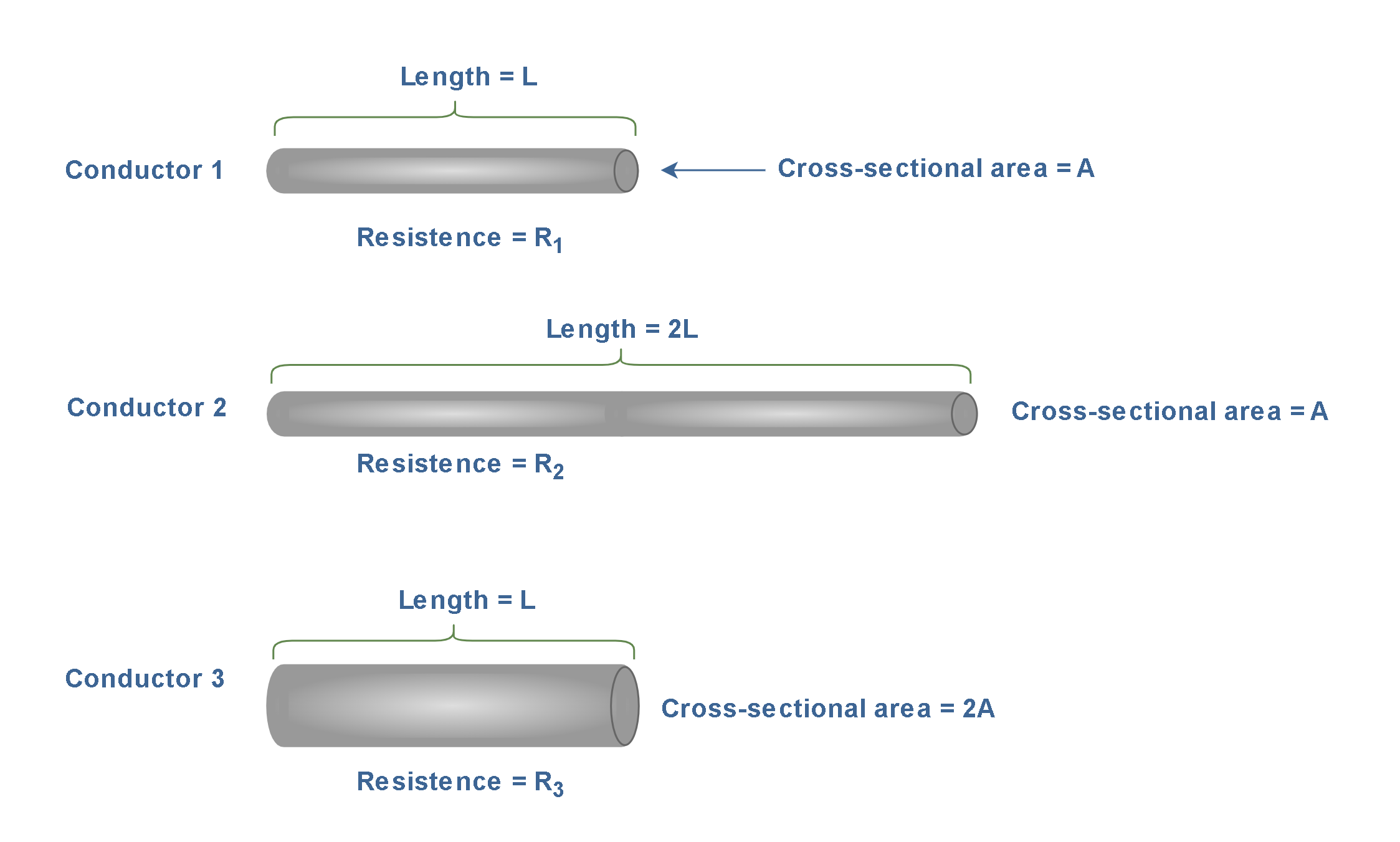
By using Equation 4, we can calculate and compare their resistances R1, R2, and R3. Conductor 2 has the same cross-sectional area as conductor 1 (= A), but with doubled length (= 2L). Therefore, its resistance (R2) is 2 times the resistance of conductor 1, i.e., R2 = 2 ρl/A = 2R1. Conductor 3 has the same length as conductor 1 (= L), but with doubled cross-sectional area (= 2A). Therefore, its resistance (R3) is half of the resistance of conductor 1, i.e., R3 = ρl/2A = R1/2.
Figure 3 illustrates how the resistance of a conductor changes based on its physical dimensions, even when the material properties remain the same.
Because the resistance (R) of a conductor with a uniform cross-section is proportional to the resistivity according to Equation 3, the temperature variation of resistance can be written as Equation 5:

where ‘R’ is the resistance at some temperature T (in Celsius degrees), ‘R0’ is the resistance at some reference temperature ‘T0’ (usually 20°C), and ‘α’ is the temperature coefficient of resistivity.
Ohm’s Law For Circuit Theory
When a voltage (potential difference) ∆V is applied across the ends of a metallic conductor as in Figure 1, the current ‘I’ in the conductor is found to be proportional to the applied voltage (I ~ ∆V).
Then, we can write Equation 6 where the proportionality constant is the resistance of the conductor:

where ‘I’ is the current (units of Ampere) and ‘∆V’ is the voltage (units of volts) and ‘R’ is the resistance measured in SI units of volts per ampere, called ohms (Ω).
By definition, if a potential difference of 1 V across a conductor produces a current of 1 A, the resistance of the conductor is 1 Ω. This is another well-known definition for resistance in circuit theory.
This statement of Equation 6 is known as Ohm’s law for circuit theory, after Georg Simon Ohm (1789–1854), who was the first German physicist to conduct a systematic study of electrical resistance. This is in fact a special case of Equation 1. We continue to use this traditional form of Ohm’s law when discussing electrical circuits. This law has lots of practical applications in electrical engineering.
The concepts of electric current, voltage, and resistance can be compared to the flow of water in a river. As water flows downhill in a river of constant width and depth, the flow rate (water current) depends on the steepness of the origin of the river and the effects of rocks, the riverbank, and other obstructions. The voltage difference is analogous to the steepness, and the resistance to the obstructions.
Based on this analogy, it seems reasonable that increasing the voltage applied to a circuit should increase the current in the circuit. Also, increasing the resistance in a circuit will lower the electric current.
Ohm’s law is a practical relationship valid only for certain materials. Materials that obey Ohm’s law, and hence have a constant resistance over a wide range of voltages, are said to be ohmic. Materials having a resistance that changes with voltage or current are nonohmic. In other words, ohmic materials have a linear current-voltage relationship and a constant slope over a large range of applied voltages as depicted in Figure 4 (a). But nonohmic materials have a nonlinear current-voltage relationship (without a constant slope) as shown in Figure 4 (b).
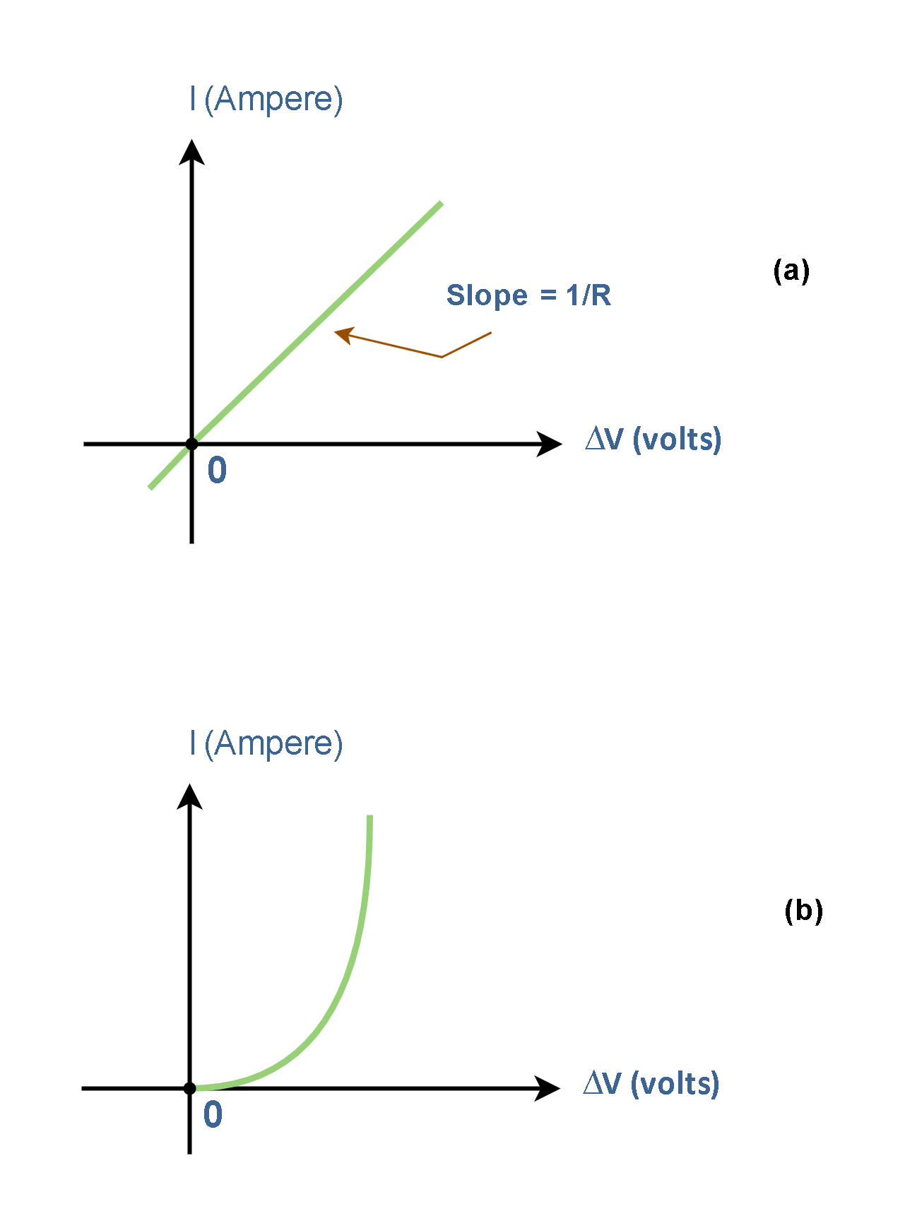
Most simple resistors in electronic systems have linear current-voltage relationships with a constant slope, while modern semiconductor electronic devices, such as diodes and transistors, have nonlinear current-voltage relationships and they do not obey Ohm’s law.
Summary
- Conductivity (σ) relates current density to the applied field directly.
- Conductivity represents a material’s ability to allow electric current, and it is expressed in units of S/m, where 1S = 1Ω-1.
- Ohm’s Law, which specifies the relationship between electric field intensity and current, applies only to conduction current.
- In a perfect vacuum, conductivity is zero.
- Resistivity arises due to collisions between the electrons with fixed atoms inside the conductor. These collisions inhibit the movement of charges in much the same way as would a force of friction.
- Resistivity (ρ) is the property of a conductor that opposes the flow of electric current and it is independent of the shape and size of the materials but depends on the nature and temperature.
- Conductivity and resistivity properties are reciprocal.
- Resistance depends on both resistivity and the geometry of the device.
- In metals, conductivity generally decreases with increasing temperature while in semiconductors and insulators, it often increases with temperature.
- Ohm’s Law in circuit theory, states that the potential drop across a resistor is equal to the current times the resistance.
More tutorials in Electromagnetism
- Electric Conductivity, Resistance and Ohm’s Law
- Steady Current And Current Density
- Electric Displacement and Electrostatic Energy
- Electrostatic Fields In Material Bodies
- The Electric Flux And Gauss’s Law
- Electric Potential In Uniform Fields
- Electric Potential In Nonuniform Fields
- The Electric Field
- The Electric Force


