
Electrostatic Fields In Material Bodies
- Kamran Jalilinia
- kamran.jalilinia@gmail.com
- 15 min
- 62 Views
- 0 Comments
- 0 Likes

Electronic Polarization Of Atoms In Static Electric Field
In previous discussions, we have considered the effect of an electric field on charges in free space. In this section, we shall study the effect of electric fields on material media. Matter, which is made of atoms or molecules, comes in many varieties—solids, liquids, gases, metals, woods, and glass—and these substances do not all respond in the same way to electrostatic fields.
In free space, the electric field is defined as force per unit charge. This implies that the electric field in free space is a measurable quantity. However, measuring the electric field inside materials may be very difficult or impractical. Instead, we can focus on the external effects of a material body using external measurements.
In general, we classify materials according to their electrical properties into three types: conductors, semiconductors, and insulators (or dielectrics).
In terms of the orbital atomic model, each atom consists of a positively charged nucleus with orbiting negatively charged electrons in a cloud surrounding the nucleus.
In conductors, which are substances that contain a large number of mobile charges, the electrons in the outermost shells of each atom, are very loosely held and migrate easily from one atom to another. Most metals belong to this group. In a typical metal body, this means many of the electrons (one or two per atom) are not associated with any particular nucleus, but roam around at will.
In dielectrics, by contrast, every electron is attached to a specific atom or molecule, and all charges can move a bit within the atom or molecule. Such microscopic displacements are not as large as the rearrangement of charge in a conductor, but their cumulative effects account for the characteristic behavior of dielectric materials.
The electrical properties of semiconductors fall between those of conductors and insulators and they can pass a relatively small number of freely movable charges.
An atom as a whole is electrically neutral. When a neutral atom is placed in an electric field E, these two regions of charge within the atom are influenced by the field: the nucleus is pushed in the direction of the field, and the cloud of electrons the opposite way. Thus, the center of charge of the electron cloud in an atom moves slightly concerning the center of charge of the nucleus. This temporary separation of charge from their equilibrium position makes one side of the atom somewhat positive and the opposite side somewhat negative. This phenomenon creates a dipole moment in the atom and is called electronic polarization.
Figure 1 shows a model of an atom in a neutral condition and without any external electric field.
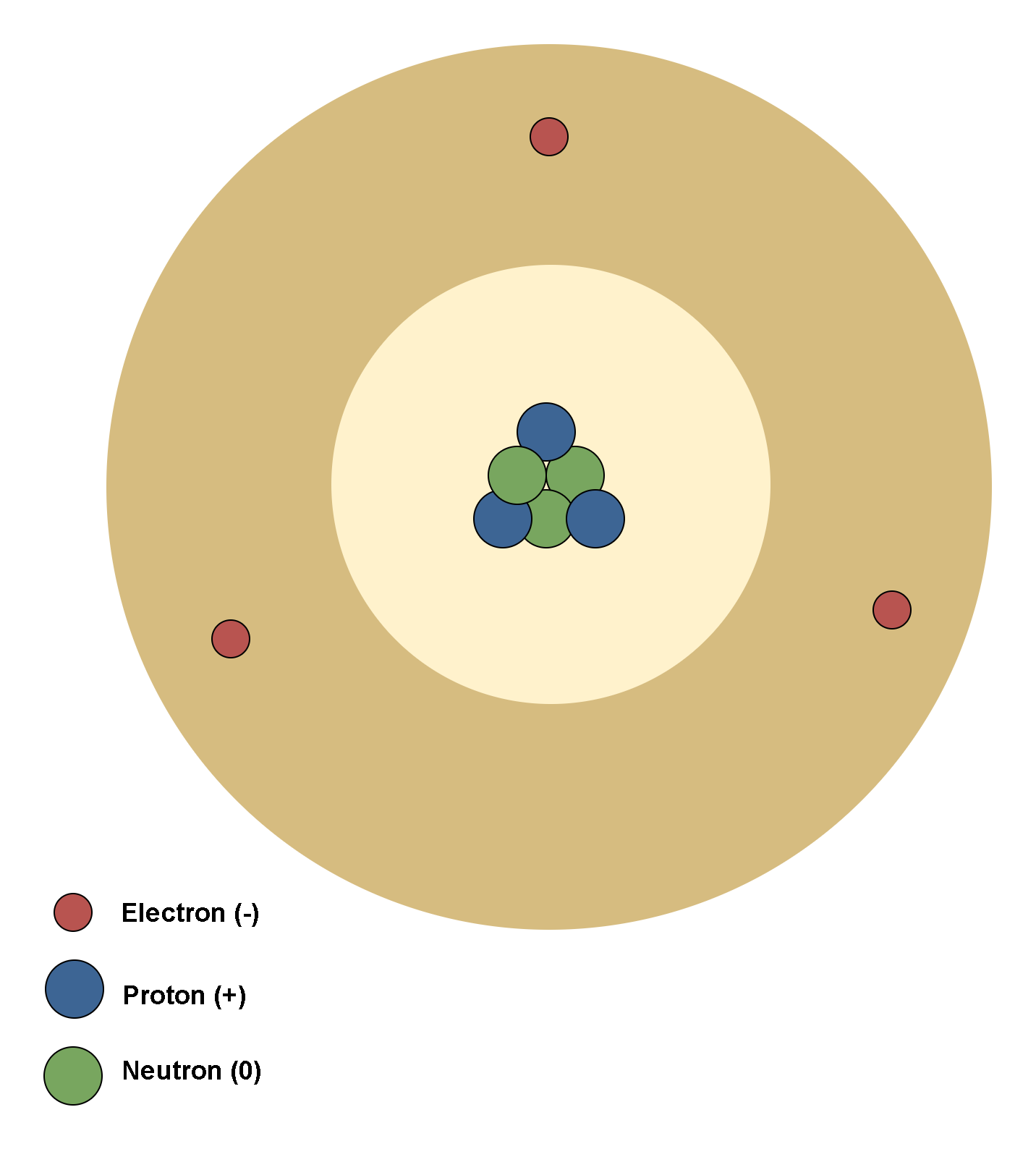
Figure 2 shows the effect of an external electric field on the polarization of the atom.
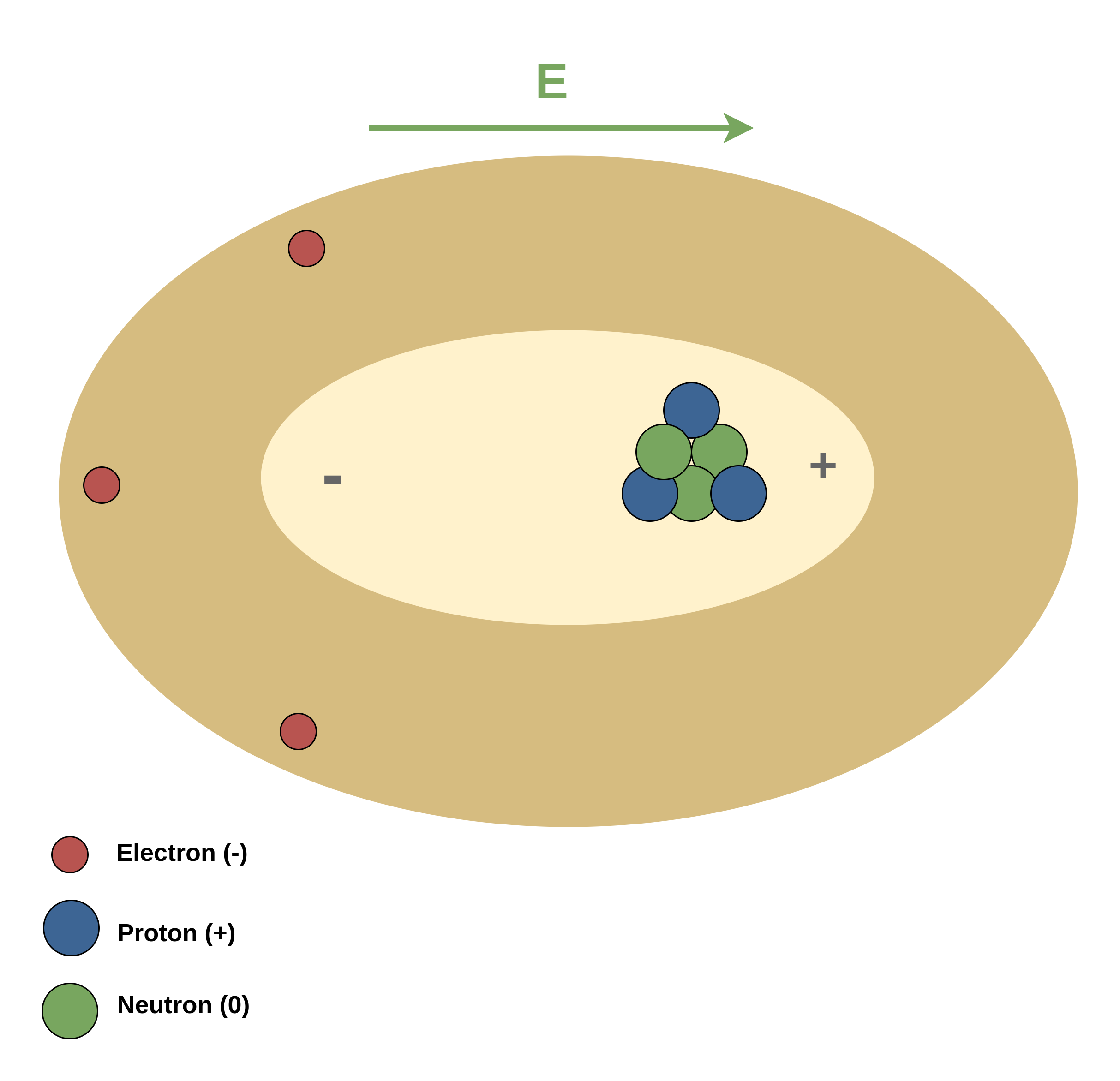
It is clearly shown that due to the direction of the external electric field E, the center of positive charges (protons) is displaced to the right side, and the center of negative charges (electrons) is displaced to the opposite side.
Molecular Polarization Of Dielectrics In Electric Field
Although the molecules of most dielectrics are normally neutral, the presence of an external electric field causes a force to be exerted on each charged particle and results in small displacements of positive and negative charges in opposite directions. Although these displacements are small compared to atomic dimensions, they can polarize a dielectric material and create electrical dipoles. These induced electric dipoles will modify the electric field inside the dielectric material.
In terms of molecular behavior in electric fields, dielectrics can be classified into two main types. Thus, when we put a piece of dielectric in an electric field, there are two possibilities happen, depending on the type of molecules in a dielectric:
1. Dielectrics with nonpolar molecules: These dielectric substances consist of neutral molecules. When they are placed in an external electric field, the field induces some tiny dipoles in molecules. This occurs because the external field tends to stretch the molecules and separate the centers of negative and positive charges slightly.
Figure 3 shows a nonpolar dielectric slab with no external electric field applied (Eex = 0). The circles represent the electrically neutral molecules within the slab. Then, the electric field inside this dielectric slab is also zero (Ein = 0).
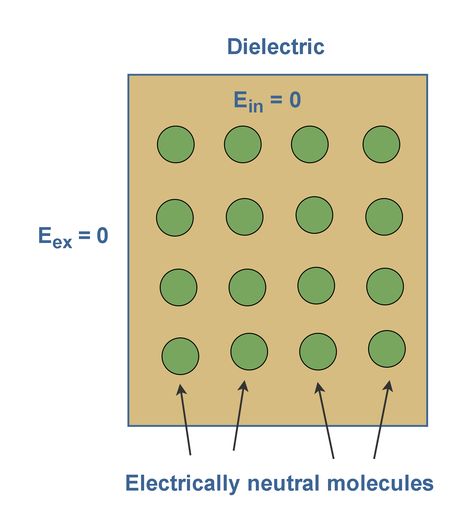
Figure 4 shows that the slab is placed inside an external uniform field Eex. The result is a slight separation of the centers of the positive and negative charge distributions within the slab. It means each molecule would become a tiny dipole, with positive and negative ends slightly separated.
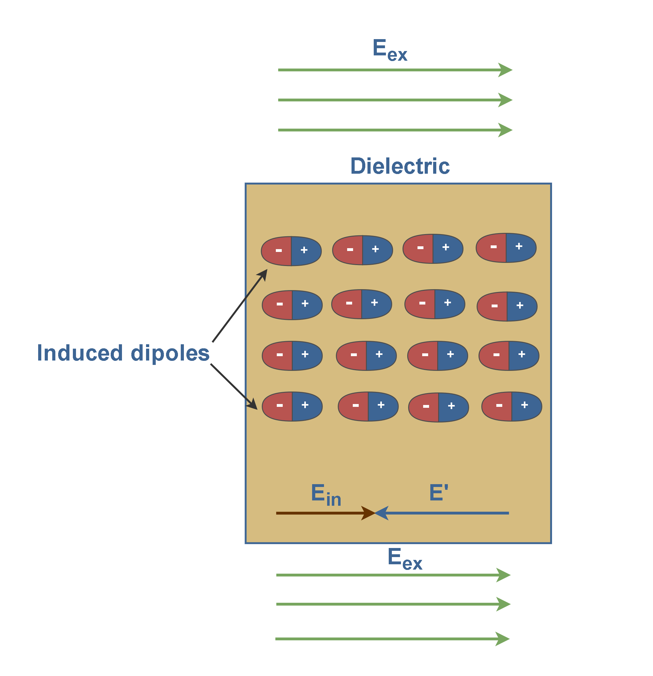
In Figure 4, there are long strings of induced dipoles. Along the line, the head of one effectively cancels the tail of its neighbor, but in the end, there are two charges left over. This produces a positive charge on one face of the slab (due to the positive ends of dipoles there) and a negative charge on the opposite face (due to the negative ends of dipoles there).
These are not free charges, and they cannot contribute to the conduction process. Rather, they are bound in place by atomic and molecular forces and can only shift positions slightly in response to external fields. They are called bound charges.
Figure 4 also shows that these bound charges produce a net electric field E’ in the direction opposite that of the applied electric field Eex. The resultant field Ein inside the dielectric (the vector sum of fields Eex and E’) has the direction of Eex but is smaller in magnitude. Equation 1 explains this fact.

2. Dielectrics with polar molecules: In such dielectrics, molecules usually consist of two or more dissimilar atoms. The molecules of such dielectrics, like the water molecule (H2O), have permanent electric dipoles.
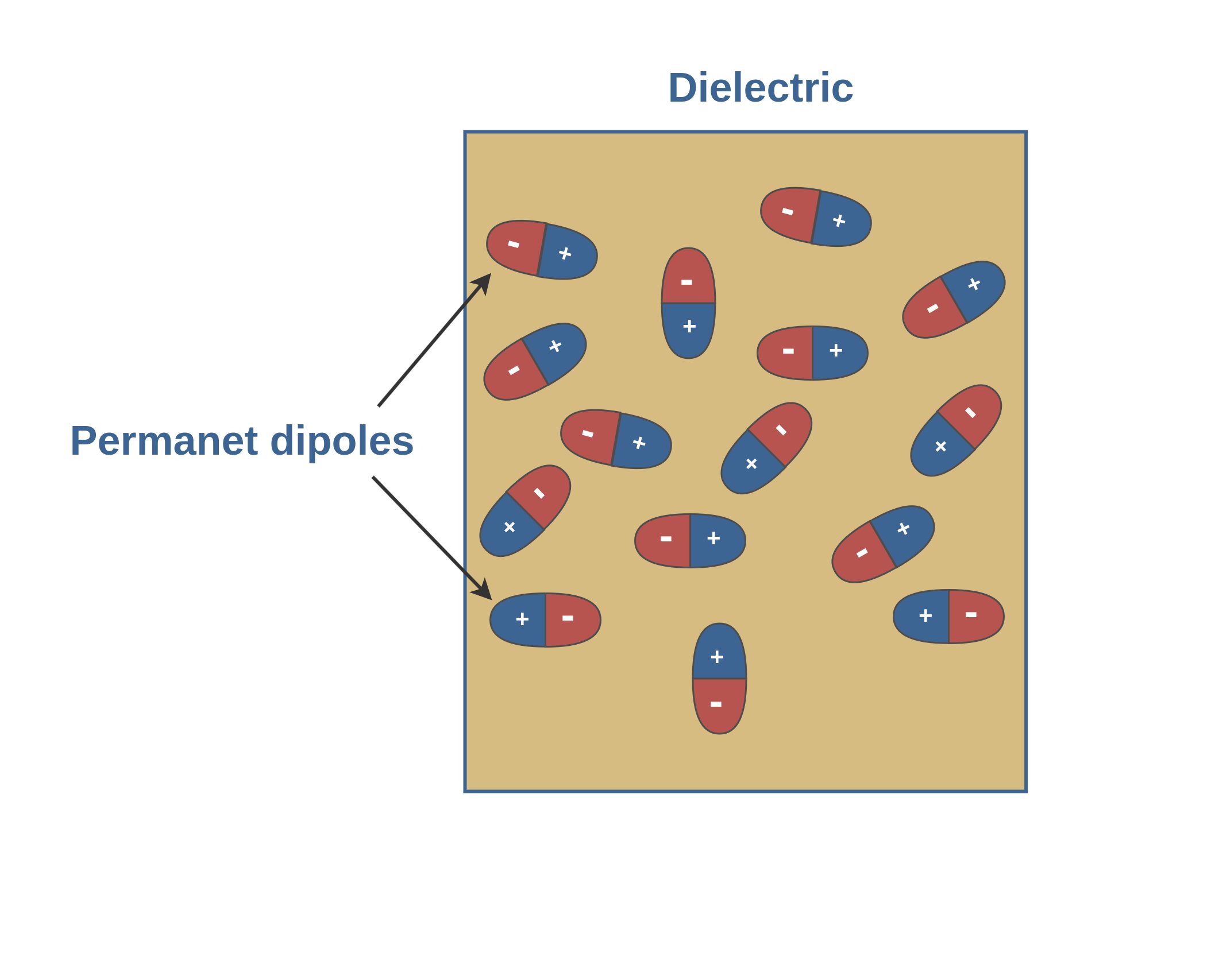
When there is no external field, the individual dipoles in a polar dielectric are randomly oriented, producing no net electric field macroscopically (Figure 5).
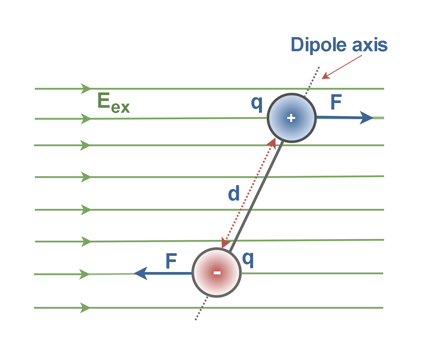
An applied electric field will exert a rotational force F on the individual dipoles and tend to align their axes with the field direction like that shown in Figure 6. The dipole moments (q × d) of polar molecules are of the order of 10-30 Coulomb-meters.
Thus, when an external electric field is present in polar dielectrics, all the electric dipole moments tend to line up with the external electric field as in Figure 7.
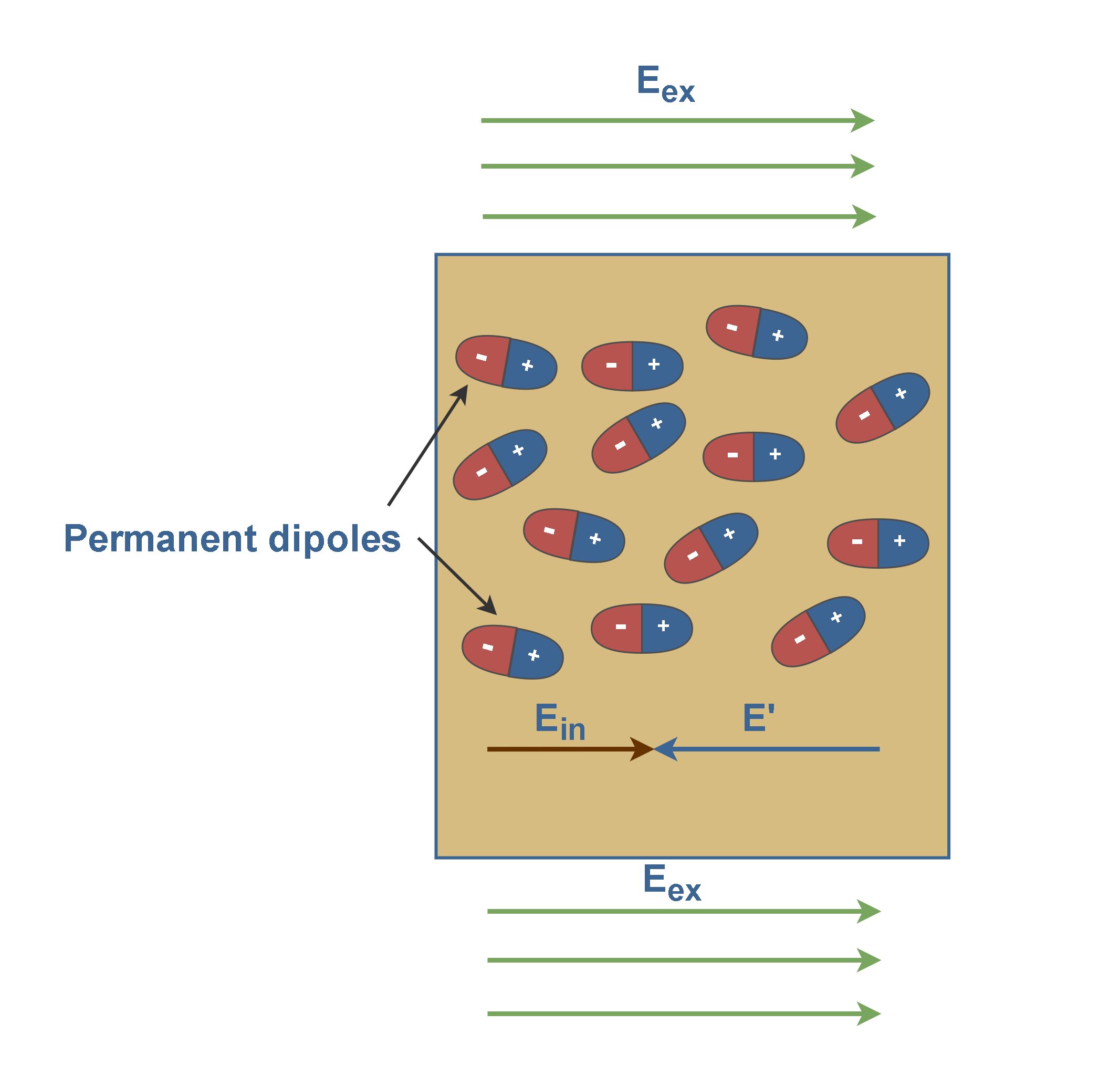
Because the molecules are continuously jostling each other as a result of their random thermal motion, this alignment is partially and not complete, but it might become more complete as the magnitude of the applied field is increased.
Therefore, the principal mechanisms by which electric fields can change the charge distribution of a dielectric atom or molecule are the rotating and stretching of tiny electric dipoles.
In conclusion, the effect of both polar and nonpolar dielectrics is similar to weaken any externally applied field within them.
Permittivity Of Dielectrics
In a conductor, the outer electrons of an atom are easily detached and migrate readily from atom to atom under the influence of an electric field. In a dielectric, on the other hand, the electrons are so well bound or held near their equilibrium positions that they cannot be detached by the application of ordinary electric fields. Hence, an electric field produces no migration of charge in a dielectric, and, in general, this property makes dielectrics act as good insulators. Paraffin, glass, and mica are examples of dielectrics.
The characteristic that all dielectric materials have in common, whether they are solid, liquid, or gas, and whether or not they are crystalline in nature, is their ability to store electric energy. An important characteristic of a dielectric is its permittivity (ϵ). It is the ability of a substance to hold an electrical charge.
Since the permittivity of a dielectric is always greater than the permittivity of vacuum ϵ0, it is often convenient to use the relative permittivity ϵr, of the dielectric, i.e., the ratio of its absolute permittivity to that of vacuum. Equation 2 explains the definition of ϵr.

- where ϵr = relative permittivity of dielectric,
- ϵ = permittivity of dielectric,
- ϵ0 = permittivity of vacuum = 8.85 x 10⁻¹² F.m-1.
Whereas ϵ and ϵ0 are expressed in Farads per meter (F/m), the relative permittivity ϵr, is a dimensionless ratio.
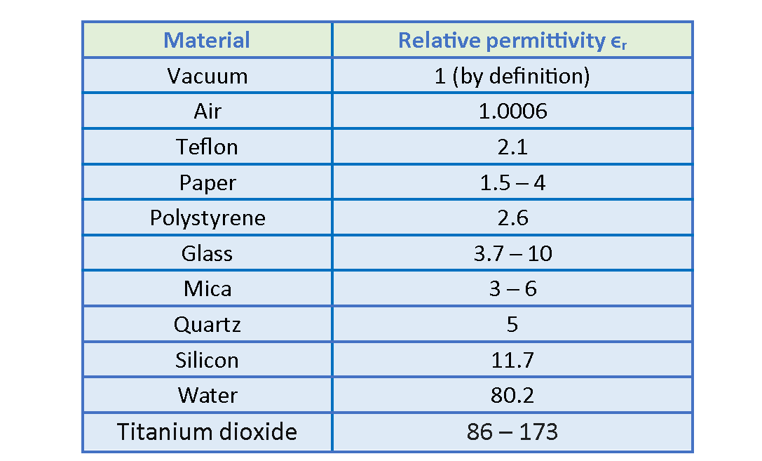
The relative permittivity of some media is shown in Table 1, where the values are for static (or low-frequency) fields and, except for vacuum or air, are approximate. The absolute permittivity of vacuum is unity by definition. Note that ϵ0, for air is so close to unity that for we can consider air equivalent to vacuum. Notice that ϵr is a constant greater than 1, for all other materials.
Dielectrics Inside A Capacitor
In our previous articles, we considered capacitors with air dielectric between their plates. Here we shall see how to modify and generalize that law if dielectric materials, such as those listed in Table 1, are present.
A capacitor is a device used to store electric charge. The amount of charge q a capacitor can store depends on two major factors – the voltage applied and the capacitor’s physical characteristics, such as its size and plate separation. Figure 8 shows an example of a parallel-plate capacitor that acquires charges from a battery.
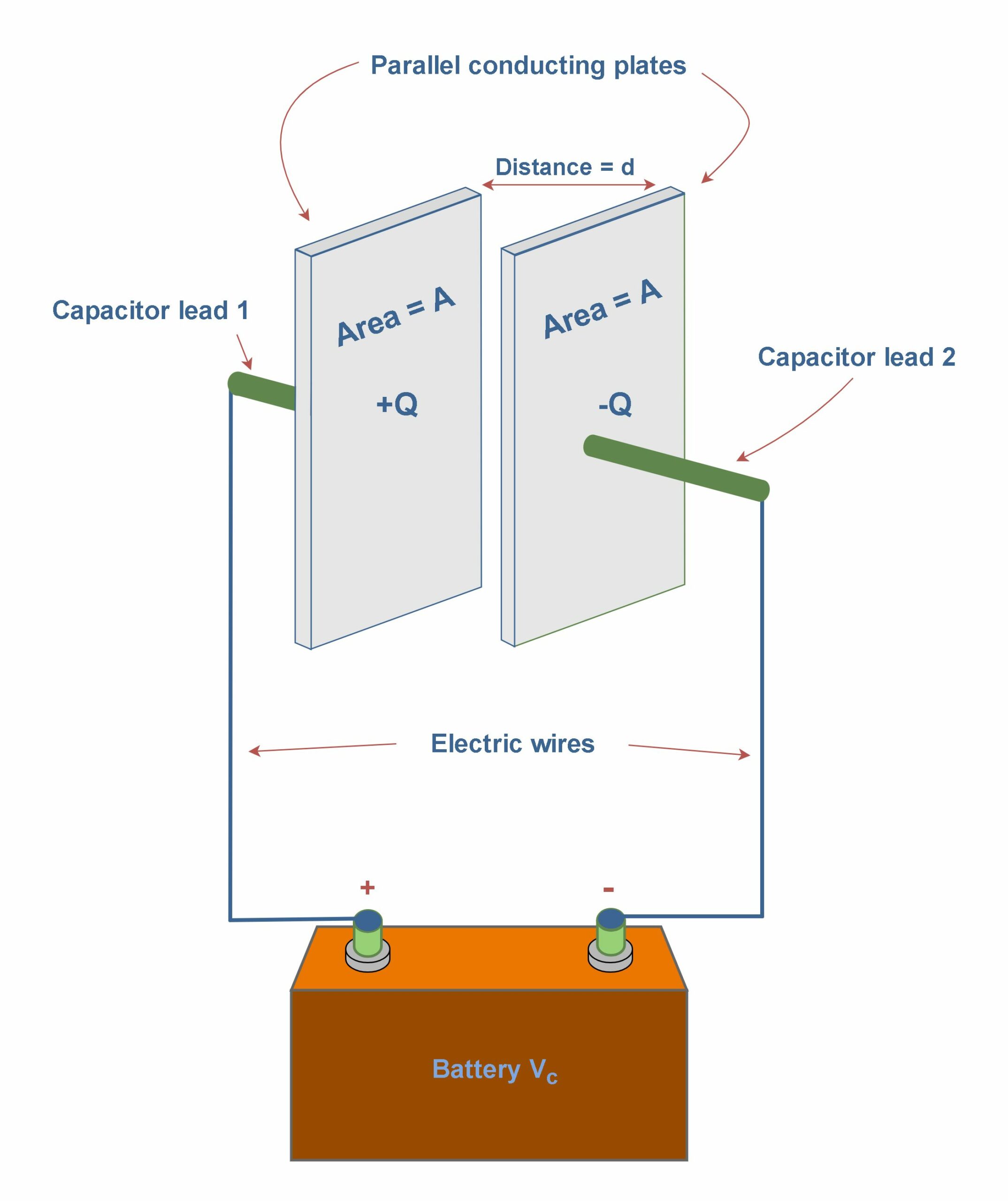
For such a parallel-plate capacitor with the air dielectric between its plates, the capacitance due to its dimensions can be written in the form of Equation 3:

where, A is the area of plates, measured in squared meters and d is the distance between plates, measured in meters. Cair is the value of the capacitance with only air between the plates measured in Farad.
Historically, in 1837, Michael Faraday first looked into this matter, if we fill the space between the plates of a capacitor with a dielectric, which is an insulating material such as mineral oil or plastic, what happens to the capacitance? He found that the capacitance increased by a numerical factor denoted as κ, which he called the dielectric constant of the insulating material. Today, this factor is also known as the relative permittivity εr and these names are used interchangeably.
Faraday discovered that, with a dielectric filling the space between the plates, the capacitance of a parallel-plate capacitor is defined as in Equation 4:

It shows that by placing a dielectric between the plates of a capacitor, the capacitance is increased by the factor κ (= ϵr). Obviously, κ and ϵr are dimensionless quantities. Even common paper can increase the capacitance of a capacitor, and some materials, such as Titanium dioxide (TiO2), can increase the capacitance more significantly.
We have already defined the capacitance of this two-conductor system as the ratio of the magnitude of the total charge on either conductor to the magnitude of the potential difference between conductors, as explained in Equation 5:

Where Q is the amount of charge (in Coulombs) on each plate and Vc is the potential difference between plates (in volts). If we rearrange the variables in Equations 4 & 5, we achieve Equation 6 which is easier to understand:

Figure 9 provides some new insight into Faraday’s experiments. Figure 9a shows a simple electrical circuit, a parallel-plate capacitor with air dielectric (Cair) is connected to a battery with an arbitrary voltage Vc. Some amounts of charge (Q) are placed and stored on the plates of the capacitor and the battery ensures that the potential difference Vc between the plates will remain constant.
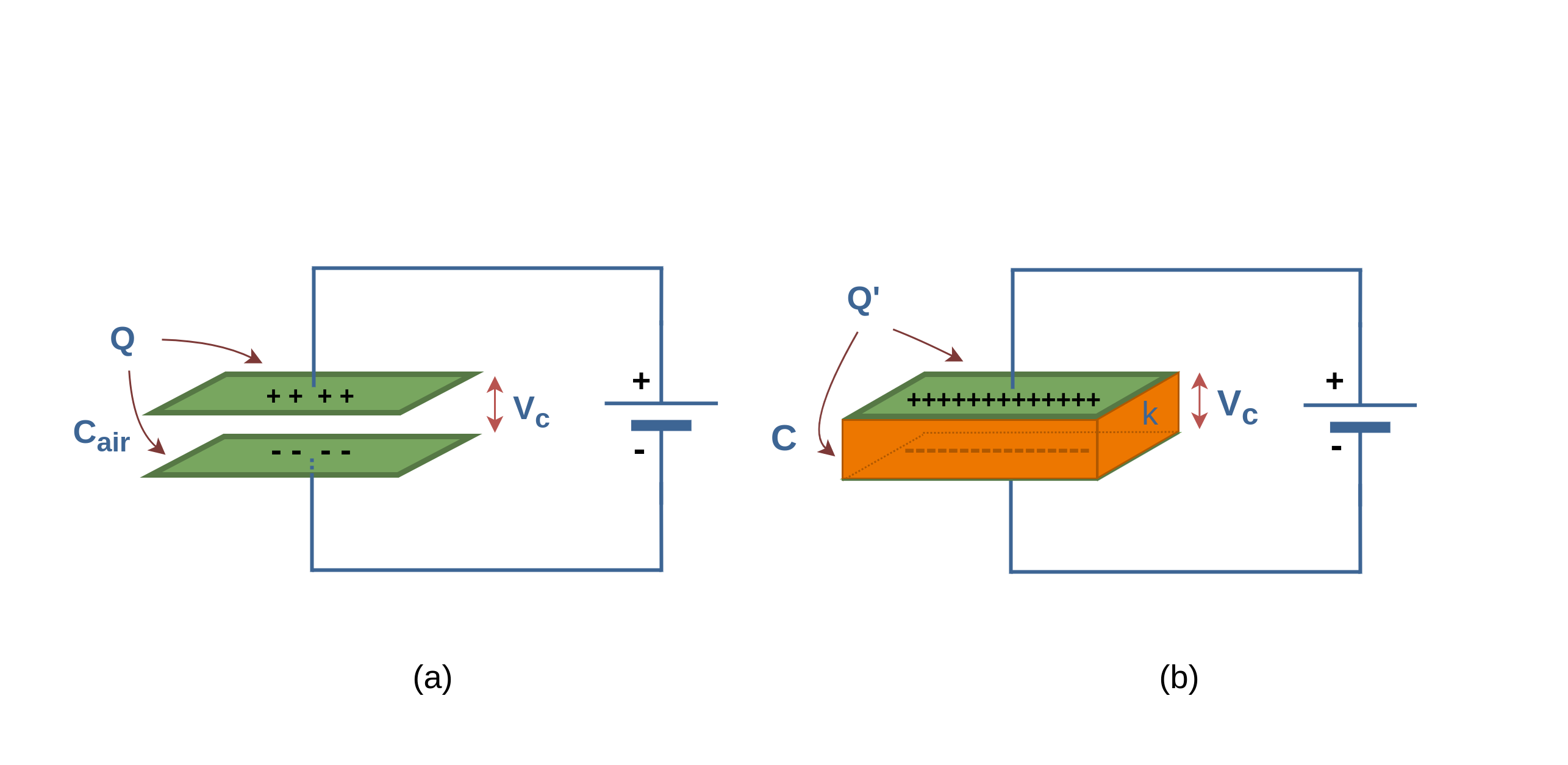
When a dielectric slab (with dielectric constant κ) is inserted between the plates, as shown in Figure 9b, because of increasing the capacitance C, the primary charge Q on the plates increases by the factor κ; according to Equation 6. Here, the battery delivers the additional charge to the capacitor plates to reach the new amount of Q’, where, Q’ > Q. So, when the potential difference between plates of a capacitor is maintained, as by the battery, the effect of a dielectric is to increase the charge on the plates.
In Figure 10a the battery is replaced by a voltmeter (a device for measuring potential difference). A capacitor cannot discharge through a voltmeter. Therefore, the primary charge Q must remain constant.
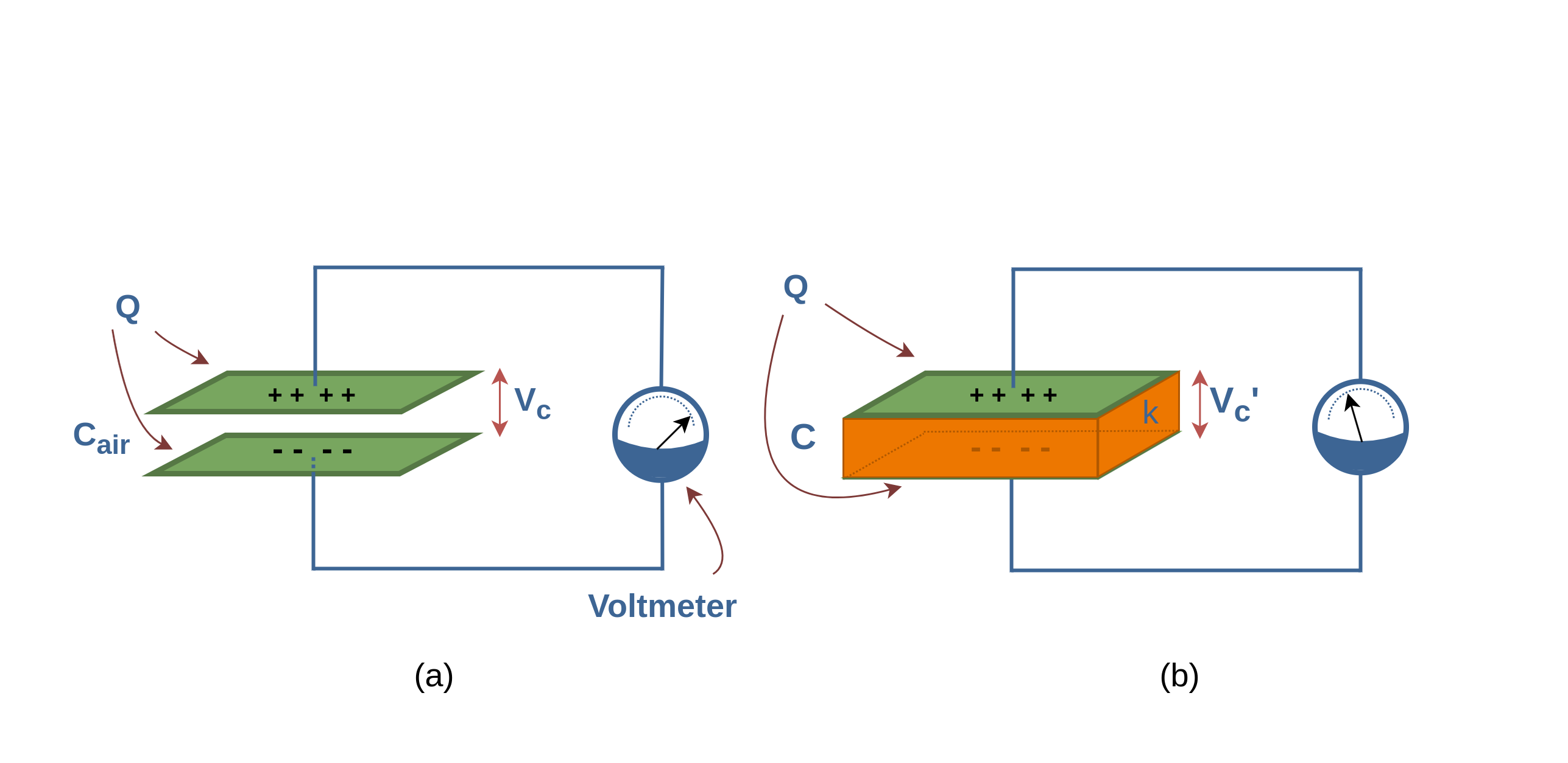
When a dielectric slab is inserted between the plates, as shown in Figure 10b, then the voltmeter shows that the potential difference (Vc’) between the plates reduces by a factor κ, it means that Vc’ < Vc.
Finally, both these observations, constant voltage (with battery) and constant charge (with voltmeter), are consistent with the increase in capacitance caused by the dielectric. Equation 6 confirms these results.
Dielectric Strength
When the electric field in a dielectric is sufficiently large, it begins to pull the electrons completely out of the molecules, and the dielectric becomes conducting. Dielectric breakdown is said to have occurred when the dielectric becomes conducting. This phenomenon could be due to electron avalanche or ionization processes.
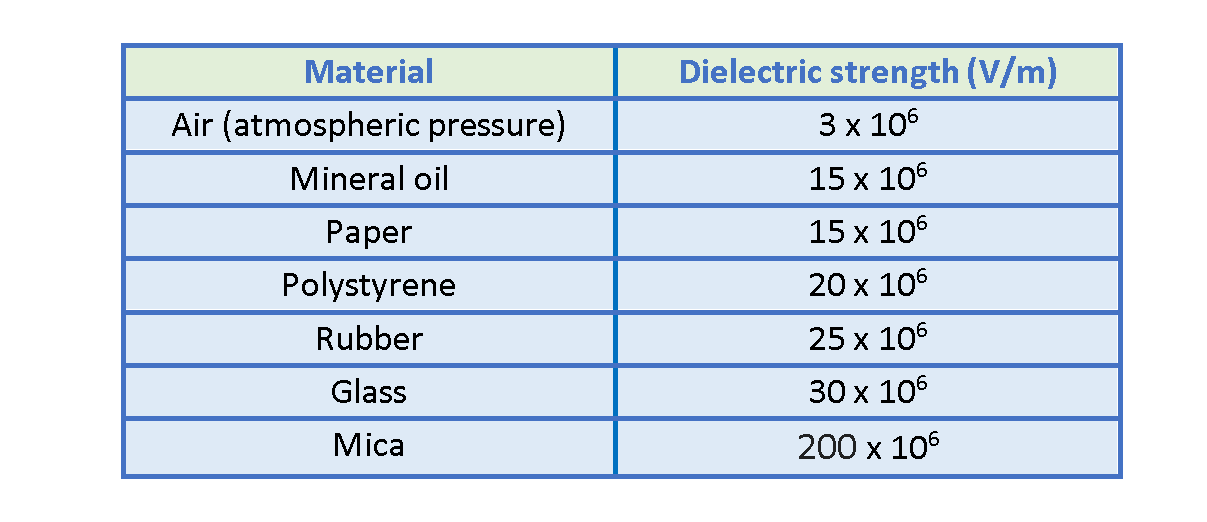
Hence, every dielectric material has a characteristic dielectric strength, which is the maximum value of the electric field that it can tolerate without breakdown. For example, this parameter for air is about 3 x 10⁶ V/m. When the electric field intensity exceeds this value, the air breaks down and corona discharge happens. Sometimes it is observable as lightning between clouds in nature.
A few dielectric strength values are listed in Table 2.
Summary
- Conductors are substances that contain a large number of charges that are free to move about through the material.
- Dielectrics possess no free charges that can drift around under the control of an externally applied electric field.
- Electronic Polarization occurs when an electric field distorts the negative cloud of electrons around a positive atomic nucleus in a direction opposite the field.
- In insulators or dielectrics, all charges are bound to their atoms or molecules, and they can be forced to move by only tiny distances, with positive charges going one way and negative charges in the opposite direction.
- A dielectric in which this displacement has taken place is said to be polarized.
- Nonpolar molecules do not have permanent dipole moments.
- The molecules of polar dielectrics possess permanent dipole moments, even in the absence of an external field.
- In the absence of an external electric field, they have random orientations.
- In polar molecules, each permanent dipole will experience a force by the external polarizing field, tending to line it up along the field direction.
- When a lot of little dipoles are produced pointing along the direction of the field, the material becomes polarized.
- The net charges at the ends are called bound charges because they cannot be removed.
- The alignment of the electric dipoles in a polarized dielectric produces a net electric field inside the dielectric that is directed opposite the applied field and is smaller in magnitude.
- The relative permittivity informs us about the electrical storage ability of an insulator.
- The historical term for the relative permittivity was dielectric constant.
- Because air is mostly space, its measured dielectric constant is only slightly greater than unity.
- The dielectric strength is the maximum electric field that a dielectric can tolerate or withstand without breakdown.
Please follow and like us:
More tutorials in Electromagnetism
- Electric Conductivity, Resistance and Ohm’s Law
- Steady Current And Current Density
- Electric Displacement and Electrostatic Energy
- Electrostatic Fields In Material Bodies
- The Electric Flux And Gauss’s Law
- Electric Potential In Uniform Fields
- Electric Potential In Nonuniform Fields
- The Electric Field
- The Electric Force
Subscribe
Login
0 Comments