Light Emitting Diode
- Muhammad Shahid
- m_shahid@live.co.uk
- 12 min
- 1.986 Views
- 0 Comments
The Light Emitting Diode
The light-emitting diode commonly referred to as LED is a special type of diode with characteristics similar to that of a normal diode. The LED is a device that converts electrical energy into light energy. The LED is a current-driven semiconductor device and when forward-biased emits light of narrow bandwidth depending on the construction of the LED. The emitted light may either be in the visible or non-visible spectrum. LEDs can be categorized as the most widely used semiconductor devices and are mostly used in televisions, colored displays and in road lights, etc.
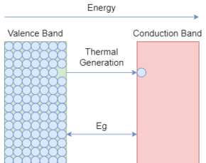
The LEDs are fabricated to have thin layers of heavily doped semiconductor materials. The semiconductor material and its doping level characterize the emitted light when forward-biased. The different semiconductor materials and the doping levels emit light of different wavelengths. The emitted light in the form of photons is the energy released by the conduction electrons when they recombining with the holes of the valence band. Whilst recombining, a sufficient amount of energy is released to produce monochromatic light by photon.
Physical Construction
The physical appearance and construction of LEDs are different from that of the conventional diode. Normally, the PN junction of a LED is covered by strong transparent epoxy resin having a hemispherical shape. This construction not only helps in protecting the delicate construction of LED but also acts as a lens to concentrate/ focus the emitted light. The light emitted by the PN junction is not of significant strength and would reflect away unnoticeable. However, the construction of domed shaped cover helps the light to focus, strengthen, and to be more prominent.
The LEDs with monochromatic light have two legs i.e. anode (+) and cathode (-). The cathode of an LED can be identified by either a flat surface/ notch or by shorter lead. The LEDs are replacing conventional light bulbs because of their efficiency and construction size. The conventional light sources dissipate heat and losses much of the energy whilst LEDs do not heat up producing minimum voltage drop across them. Being an electrostatic device, the LED can be constructed into very small sizes and shapes depending on the application requirements.

Composition of Light Emitting Diode
The composition of the PN junction is selected in a such way to emit a specific wavelength/ color and, as such, the semiconductor materials are deliberately chosen to attain this. The semiconductor materials used in conventional diodes are Silicon and Germanium, whereas, in LEDs, the semiconductor compounds are used such as Gallium Phosphide (GaP), Silicon Carbide (SiC), Gallium Arsenide Phosphide (GaAsP), Gallium Arsenide (GaAs), or Gallium Indium Nitride (GaInN), etc. These compound semiconductors are made by mixing semiconductors in certain ratios/ mixtures to strengthen a specific wavelength.
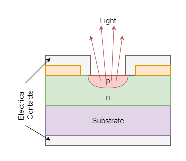
The different compounds and mixing ratios produce light of specific bandwidth in the light spectrum and also characterize the intensity of light emitted.
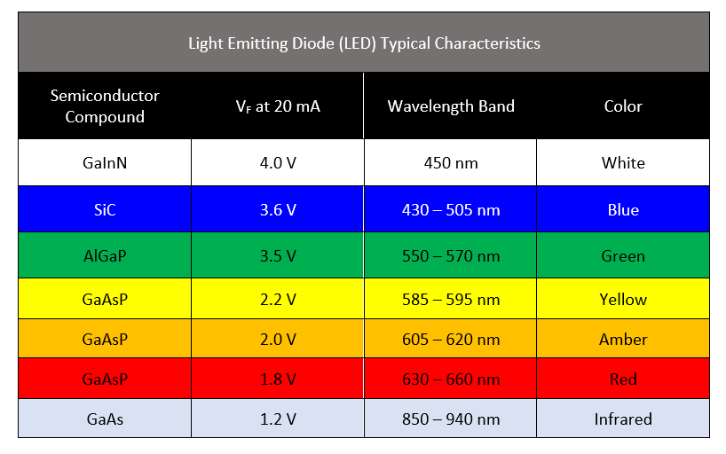
From the above chart, it is clear that what color is emitted by which semiconductor compound and its wavelength. The LED’s cover is usually made of color belonging to emitted light by the PN junction. It is merely to indicate light the color of LED and, additionally, to enhance the output of emitted light.
The most common and cheaply available colors are Red, Green, and Blue which are the primary colors easily produced by semiconductor compounds. Other colors are expensive and are produced by mixing the primary colors.
Types of Light Emitting Diodes
- Gallium Arsenide (GaAs): Infrared
- Gallium Arsenide Phosphide (GaAsP): Red, Infra-red, and orange
- Aluminium Gallium Arsenide Phosphide (AlGaAsP): Red (Bright), orange, and yellow
- Gallium Phosphide (GaP): Red, yellow and green
- Aluminium Gallium Phosphide (AlGaP): Green
- Gallium Nitride (GaN): Emerald green
- Gallium Indium Nitride (GaInN): Ultraviolet, green (bluish), and blue
- Silicon Carbide (SiC): Blue (substrate)
- Zinc Selenide (ZnSe): Blue
- Aluminium Gallium Nitride (AlGaN): Ultraviolet
Voltage Drop and Series Resistance
Similar to conventional diode, the LED is current driven and a certain voltage drop occurs when put in forward-biased mode. The forward voltage drop (VF) ranges from 1.2V to 4.0V and is dependent on the type of compound material is used in the LED. The LED emits a light when a voltage greater than the forward voltage drop is applied and the current flows through it. The excessive current flow can damage the sensitive PN junction of LED and as such requires that a proper series resistance be inserted in between the LED and voltage source. The value of series resistance should be such that it does not permit more than 80% of the rated current of the LED and should permit a sufficient amount of current to significantly brighten the LED.
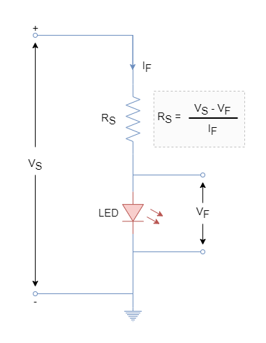
A Single LED Example
The value of series resistance can be determined using Ohm’s Law. For this purpose, the forward voltage drop (VF), forward current (IF), and supply voltage (VS) should be known. For example, for a red color LED: VF = 1.8 V, forward current limited to IF = 10 mA and voltage supply VS = 5 V. Then value of series resistance (RS) required for the red LED is:

The standard value resistance of 330 Ω is suitable for the selected red LED. The higher valued resistance is selected than the calculated one to remain under the safe limit of forward-current.
Multiple LEDs
The multiple LEDs can be connected in series and as such driving current will be the same for the LEDs in series. However, for the selection of series resistance, voltage drop (VF) for each LED must be considered. For example, a two red LED circuit will drop a voltage of 2 X 1.8 = 3.6 V and series resistance (RS) should be calculated as follow:

For two LEDs, a series resistance of 140 Ω is required to provide 10 mA of driving current.
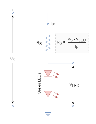
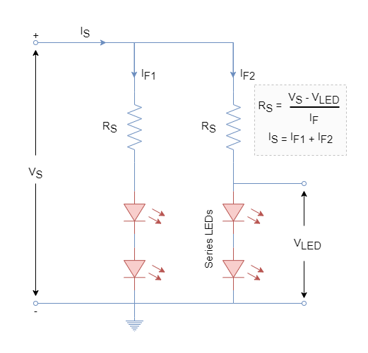
Similarly, a series and parallel combination of multiple LEDs can be made. Another branch of two red LEDs can be added in parallel to the previously constructed circuit to have a total of four LEDs driven by the same power source. The current in each branch will be same i.e., IF1 = IF2 = 10 mA. However, the source current (IS) will be doubled to drive the four LEDs.

Controlling LEDs
The LEDs can be controlled i.e. turning ON & OFF through a number of ways. Mostly, LEDs are used in low voltage digital circuits where they are driven by microcontrollers or logic gates. The logic gate or microcontroller pin can act as input or output. When the pin is set as output it acts as a current source and as a sink in input type. The capability of current handling as source or sink varies and may range from 20 mA to 50 mA. This also indicates that a series resistor is mandatory for the digital circuit to avoid damaging the LED.
In the following figure, a TTL or CMOS logic is used to drive a LED. The value of the series resistor can be calculated in the same way described earlier. The logic gate is connected to LED as a source as well as a sink in the figure.
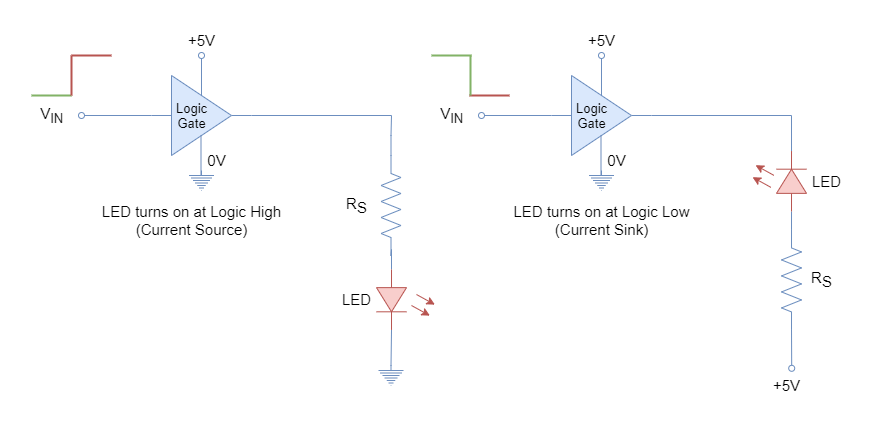
When the cathode of LED is connected to the ground and anode to the logic circuit through a resistor. Then a logic high will turn ON the LED and vice versa. The logic gate is acting as a source in this configuration. On the other hand, when an anode is connected to logic high voltage through a resistor and cathode to the logic circuit then a logic low will turn ON the LED and vice versa. Digital gate acting as a sink in this configuration.
However, due to the power and current handling limitations of logic circuits, a few of the LEDs can be connected directly to them. The external/ isolated circuitry is required to drive a large number of LEDs such as those used in bigger LED displays. A discrete component such as a transistor is used to drive fast-switching LEDs. The rating of the transistor can be carefully selected depending on the LEDs to be driven.
In the following figure, the NPN and PNP transistors are used to drive the LED from a microcontroller or a logic circuit. The series resistor is to be calculated using the following formula:

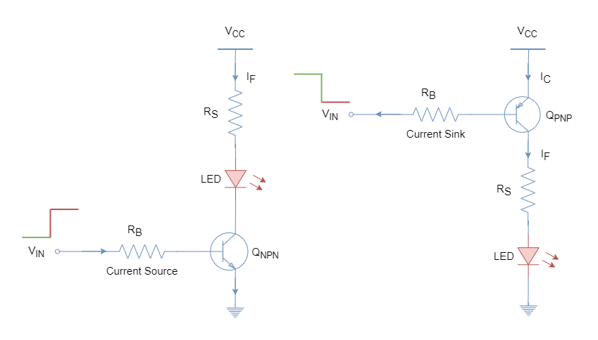
The logic high and low driving circuits using transistors are shown. The logic source is connected to the base of the transistor and switches ON & OFF the transistor depending on the logic and circuit. The switching ON of the transistor in active mode will complete the LED circuit and turns ON the LED.
Multi-colored LEDs
The single-color LEDs are most commonly used for indications purposes or in seven-segment displays. They are low cost due to simple construction and are available in different sizes & shapes. Besides single-color LEDs, the bi-color and tri-color LEDs are also most commonly used to display different states such as power or battery level, etc.
A bi-color LED has two different color LEDs connected in inverse-parallel configuration. The bi-color LED has two terminals and supply from either side produces a color. The reversal of polarity changes the color produced by the LED. These are used for checking battery polarity terminals or other indications etc.
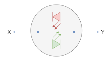
The alternating or bidirectional current applied to it turns ON & OFF both LEDs at a considerably high rate. The switching is undetectable by the naked eye and hence a mixture of both colors is observed.
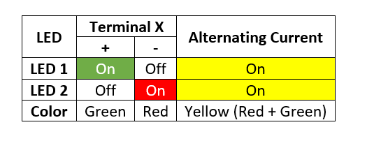
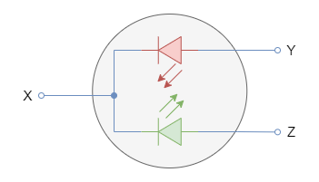
A multi-colored LED comprises red and green LEDs which are connected in parallel to each other. The color emitted by the compound LED is dependent on the driving current of both individual LEDs. The emitted color is the combination of both individual LEDs and their driving current source. The following figure shows a multi-colored LED and its driving current color table.

Applications
- Indication purposes.
- Seven segment displays for displaying numbering data.
- Handheld devices, flat-screen LED televisions, and large-screen displays for advertisement.
- Infrared-driven devices such as remote controls.
- Opto-couplers
Conclusion
- A light-emitting diode converts electrical energy into light energy.
- A light-emitting diode is a type of special diode whose PN junction is made from a compound semiconductor.
- The LED comprises of heavily doped semiconductor and has a very thin layer of PN junction.
- The forward-biased LED enables the electrons in the conduction band to recombine with the holes in the valence band. In doing so the electrons release the energy in form of photons/ light.
- The color emitted by the photons is dependent on the semiconductor compound used in the LED and its intensity is dependent on the forward biasing current.
- The wavelength of the emitted color lies in the visible or invisible light spectrum.
- The series resistance is used essentially to avoid damaging the LED(s) and the value of series resistance requires to be calculated depending on the LED type, number of LEDs, and their series/ parallel configuration.
- The LEDs are available in a variety of colors. The monochromatic colors are widely used and cheap. Whereas, bi-color and multi-color LEDs are also available but comparatively costly.
- The LED applications include, but not limited to, indication purposes, displays, televisions and large advertisement displays, etc.


