

MOD Counters
- Muhammad Shahid
- m_shahid@live.co.uk
- 15 min
- 287 Views
- 0 Comments
- 1 Likes

Introduction
MOD Counters are circuits with cascaded counters that count to a predetermined modulus value before restarting.
A counter’s function is to count by moving its contents forward by one count for each clock pulse. Counters that function in a “Count-Up” mode are those that, when triggered by a clock input, advance their sequence of numbers or states. Similarly, counters that function in a “Count-Down” mode are those that, upon activation by a clock input, lower their sequence of numbers or states. Bidirectional counters are counters that can function in both the up and down directions.
A clock signal or timing pulse from the outside activates or triggers counters, which are sequential logic devices. It is possible to build a counter such that it functions as an asynchronous or synchronous circuit. When a clock signal is applied to synchronous counters, every data bit changes simultaneously. On the other hand, the data bits in an asynchronous counter circuit change state sequentially at various times as it is not reliant on the input clock.
Then counters are sequential logic devices that are activated by an external clock (CLK) signal and follow a preset sequence of counting states. The modulus (MOD) is the number of states or counting sequences that a certain counter passes through before going back to its initial state. Stated differently, the number of states the counter counts and the counter’s dividing number are known as the modulus, or simply modulo.
MOD counter defines the number of states that a modulus counter will cycle through before returning to its initial value. For instance, a 2-bit counter with a modulus value of 4 (00 → 01 → 10 → 11 and return to 00) that counts from 002 to 112 in binary, or 0 to 3 in decimal, would be referred to as a modulo-4, or mod-4, counter. Also, note that the transition from 00 to 11 required four clock pulses.
Since there are just two bits in this straightforward example (n = 2), the maximum modulus (number of potential output states) for the counter is 2n = 22, or 4. On the other hand, counters may be made to count to any number of 2n states in their sequence by creating a single modulus counter, or “MOD-N” counter, by cascading numerous counting stages together.
To count a single input bit and provide two alternative output states, a “Mod-N” counter will thus require the “N” number of flip-flops coupled together (n being the number of bits). Keep in mind that N is always a whole integer value.
The type and modulus of a counter are determined by the number of flip-flops employed and their connection. As we can see, MOD counters have a modulus value that is an integral power of 2, i.e., 2, 4, 8, 16, and so on to form an N-bit counter.
D-type Flip-flops
“Flip-flops” are used to create MOD counters; one flip-flop may yield a count of 0 or 1, with a maximum count of 2. To build a counter, we may utilize a variety of flip-flop designs, including the S-R, J-K, J-K Master-slave, D-type, and even T-type flip-flops. But since the D-type flip-flop (DFF), also called a data latch, only requires one data input, an external clock signal, and is positive edge triggered, we shall utilize it to keep things simple.
Depending on whether you want the D-type flip-flop, like the TTL 74LS74, to change states on the positive or leading edge (0 to 1) or the negative or trailing edge (1 to 0 transition) of the clock pulse, it may be made from either S-R or J-K based edge-triggered flip-flops. Here, a positive, leading-edge triggered flip-flop will be assumed. Further details on D-type flip-flops will be discussed later.
D-type Flip-flop and Truth Table
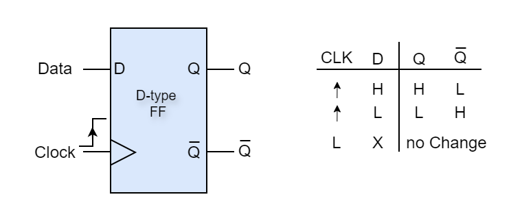
A D-type flip-flop (DFF) only has one data input, designated “D,” and one extra clock input, designated “CLK.” As a result, its operation is quite simplistic. The D-type flip-flop is a synchronous device as a result, allowing for the storage of a single data bit (0 or 1) under the control of the clock signal. This is because data from the inputs is only transmitted to the flip-flop’s output on the triggering edge of the clock pulse.
According to the truth table, the flip-flop SETs and stores a logic “1” at “Q” and a complementary “0” at (Q-BAR), when a positive clock pulse is applied and there is a logic “1” (HIGH) on the Data input. Similarly, when another positive clock pulse is delivered and there is a LOW on the Data input, the flip-flop RESETs, stores a “0” at “Q”, and outputs a “1” at (Q-BAR).
When the clock (CLK) input is HIGH, the D-type flip-flop’s output “Q” then responds to the value of the input “D.” When the clock input is LOW, the condition at “Q”, either “1” or “0” is held until the next time the clock signal goes HIGH to logic level “1”. As a result, the output at “Q” is a positive edge-triggered D-type flip-flop, since it only changes states when the clock input goes from a “0” (LOW) value to a “1” (HIGH) value. Keep in mind that negative edge-triggered flip-flops function precisely the same manner, with the exception that the triggering edge is the clock pulse’s falling edge.
Now that we understand how an edge-triggered D-type flip-flop functions, let’s see how to link a few of them to create a MOD Counter.
Divide-by-Two Counter
An effective and adaptable building block for creating a MOD counter or any other kind of sequential logic circuit is the edge-triggered D-type flip-flop. Since at the (Q-BAR), the output signal is always the inverse of the Q output signal, we can turn it into a binary divide-by-two counter using just the clock input by connecting the (Q-BAR), Output back to the “D” input as indicated and establish a feedback loop.
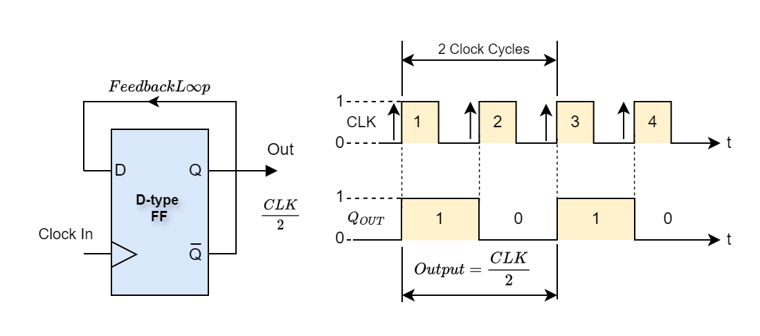
As can be seen from the timing diagrams, the flip-flop functions as a frequency divider since the frequency of the “Q” output waveform is precisely half that of the clock input. The output signal from this second DFF would be one-quarter of the clock input frequency if we added another D-type flip-flop such that the output at “Q” was the input to the second DFF, and so on. Thus, in increments of two, the output frequency for a set of “n” flip-flops is divided by 2n.
Note that this method of using this frequency division technique in sequential counting circuits is highly practical. For instance, a divide-by-60 counter might be used to convert a 60Hz mains frequency signal to a 1Hz timing signal. The 60 Hz would be divided into 10 Hz by a divide-by-6 counter, and the 10 Hz would then be sent to a divide-by-10 counter, which would divide it into a 1 Hz timing signal, pulse, etc.
MOD-4 Counter
A single flip-flop, in addition to being a 1-bit storage device, may also be conceptualized as a MOD-2 counter since, upon application of the clock signal, its sole output produces a count of two, which can be either 0 or 1. However, a single flip-flop only generates a finite counting sequence; thus, we may build a MOD counter of any value by joining more flip-flops to form a chain, which increases the counting capacity.
If a single flip-flop is considered a modulo-2, or MOD-2, counter, then adding another flip-flop would make it a MOD-4 counter, which would enable counting in four distinct stages. Essentially, the original clock input signal would be divided by four. This 2-bit MOD-4 counter’s binary sequence would thus be as follows: 00, 01, 10, and 11 as shown.
MOD-4 Counter and Timing Diagram
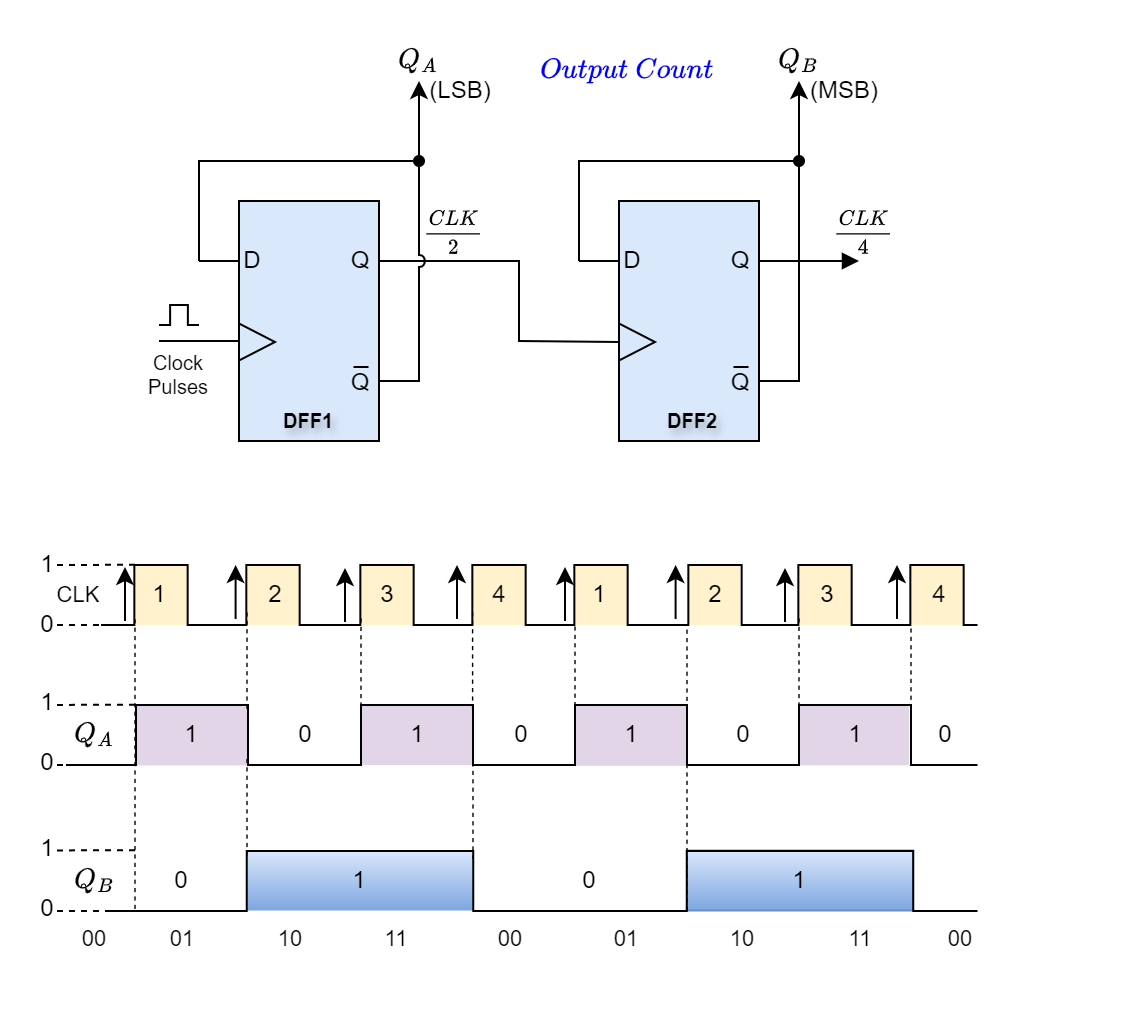
Even though this link represents an asynchronous counter, the switching transitions of QA, QB, and CLK are depicted in the timing diagram above as being simultaneous for the sake of simplicity. There would be a very slight switching delay between the outputs at QA and QB and the application of the positive-going clock (CLK) signal.
Using a truth table and state diagram, we can graphically demonstrate how this 2-bit asynchronous counter operates.
MOD-4 Counter State Diagram

As we can see from the counter’s truth table and by examining the values of QA and QB, the count equals 00 when QA = 0 and QB = 0. Following the clock pulse application, the numbers change to QA = 1, QB = 0, and there is a count of 01. Following the following clock pulse, the values shift to QA = 0, and QB = 1, resulting in a count of 10. When QA = 1, QB = 1, resulting in a total of 11. The count resets to 00 with the application of the subsequent clock pulse, and it then proceeds to count constantly upward in the binary sequence 00, 01, 10, 11, 00, 01, and so on.
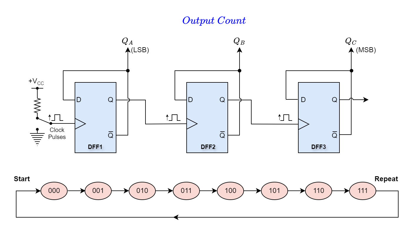
Then, we observed that a MOD-4 counter needs two flip-flops to count in four distinct steps, but a MOD-2 counter just needs one. A MOD-4 counter could easily have another flip-flop added to the end to create a MOD-8 counter, which would provide us with a 23-binary sequence that would count from 000 to 111 before resetting to 000. We could add more flip-flops indefinitely since a fourth flip-flop would create a MOD-16 counter and so on.
MOD-8 Counter and State Diagram
By constructing mod counters with a natural count of 2n states, we may therefore create counters that have mod counts of 2, 4, 8, 16, and so on, before repeating. However, sometimes it is required to have a modulus counter without a modulo that is a power of two that resets its count to zero during the regular counting procedure. As an illustration, consider a counter with a modulus of 3, 5, 6, or 10.
Counters of Modulo “m”
Both synchronous and asynchronous counters work by progressing one count at a time in a predetermined binary progression. Consequently, a “n”-bit counter easily doubles as a modulo 2n counter. However, by utilizing one or more external logic gates, we may build mod counters that will count to whatever number we need. This will cause the counter to skip a few output states and end at any count, resetting it to zero—all flip-flops have Q = 0.
Modulo “m” counters count to the “m” value and then reset to zero, as opposed to counting to all their potential states. It is evident that “m” is a lower number than 2n (m < 2n).
Thankfully, counters can also have other inputs named CLEAR and PRESET in addition to counting up or down. These allow you to preset the counter to a certain initial value or clear the count to zero (all Q = 0). Preset and Clear inputs are active-low on the TTL 74LS74.
For the sake of simplicity, let’s suppose that the flip-flops can function normally when the Clear input is equal to 0 (LOW) and that all the CLEAR inputs are coupled to one another as active-high inputs. However, regardless of the value of the subsequent clock signal, all the flip-flops will be reset to the state Q = 0, if the Clear input is at logic level “1” (HIGH).
It should be noted that since all the Clear inputs are linked, it is also possible to guarantee that the count truly begins at zero by using a single pulse to clear the outputs (Q) of each flip-flop before the counting process begins. A second ENABLE or INHIBIT input pin, found on certain bigger bit counters, enables the counter to halt the count at any time throughout the counting cycle and maintain its current state before being permitted to start counting again. This implies that the counter can be started and stopped whenever desired without causing the outputs to go to zero.
Modulo-5 Mod Counters
What steps would we need to take, if we wanted to create a MOD-5 counter? Since 2n must be more than 5 given that we know that “m = 5,” Since 8 is more than 5 and 21 = 2, 22 = 4, 23 = 8, a counter with at least three flip-flops (N = 3) is required to provide a natural binary count of 000 to 111 (0 to 7 decimal).
Applying the previous MOD-8 counter-example. The following will be the truth table for its natural count:
MOD-8 Counter and Truth Table
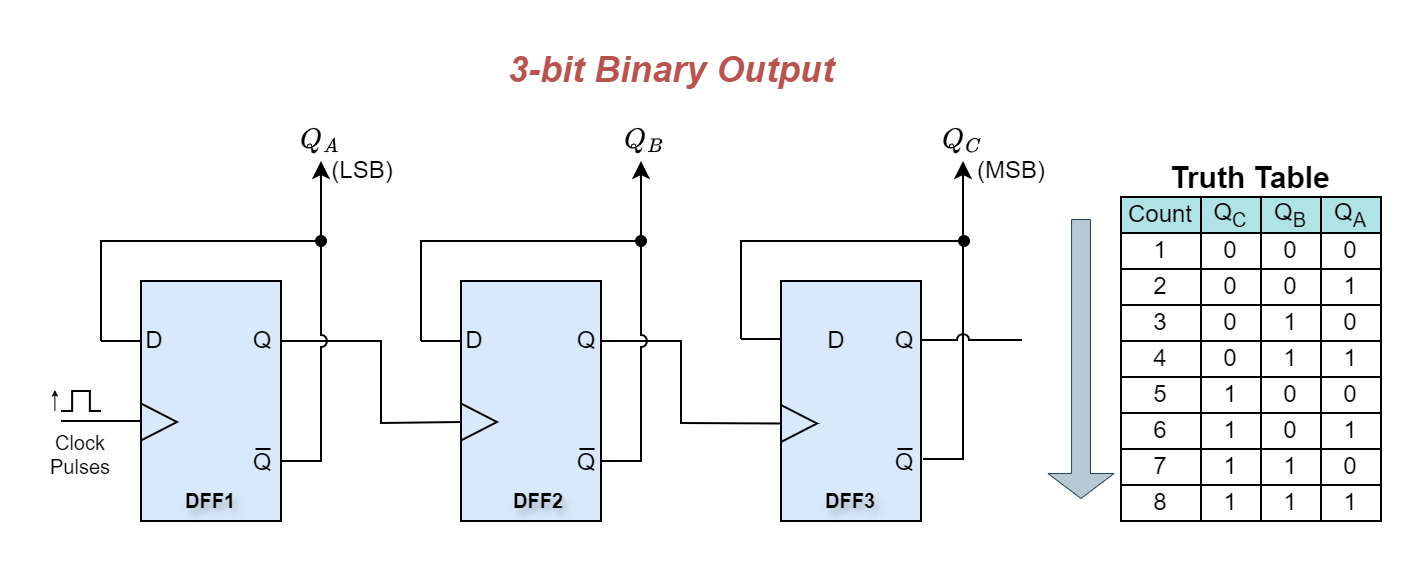
We need to change the above 3-bit counter circuit such that it will reset itself back to zero after a count of five to build a MOD-5 counter. It is a count sequence that goes like this: 1→2→3→4→5→reset, and so on.
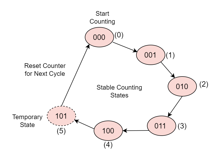
Since 000 is a legitimate count state, a MOD-5 counter would yield a 3-bit binary count sequence ranging from 0 to 4. This would give us the following binary count sequence: 000, 001, 010, 011, 100. As a result, as indicated by the state diagram below, the counter circuit must reset itself at the next counting stage, which is the count of six. In this case, the output condition would be QA = 1, QB = 0, and QC = 1 in binary.
MOD-5 Count Sequence
Using an inverter or NOT gate (TTL 74LS04) and a 3-input AND gate (TTL 74LS11), we may decode this output state of 101 (5) to get a signal to clear (Clr) the counter back to zero. The 3-bit counter outputs of QA, QB, and QC are coupled to the inputs of the combinational logic circuit, which consists of an inverter and a digital logic AND gate.
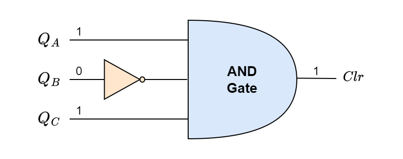
Therefore, for any combination of inputs other than the desired input sequence, the 3-input AND gate’s output will be at logic level “0” (LOW).
The output sequence count in binary code will be 000, 001, 010, 011, 100.
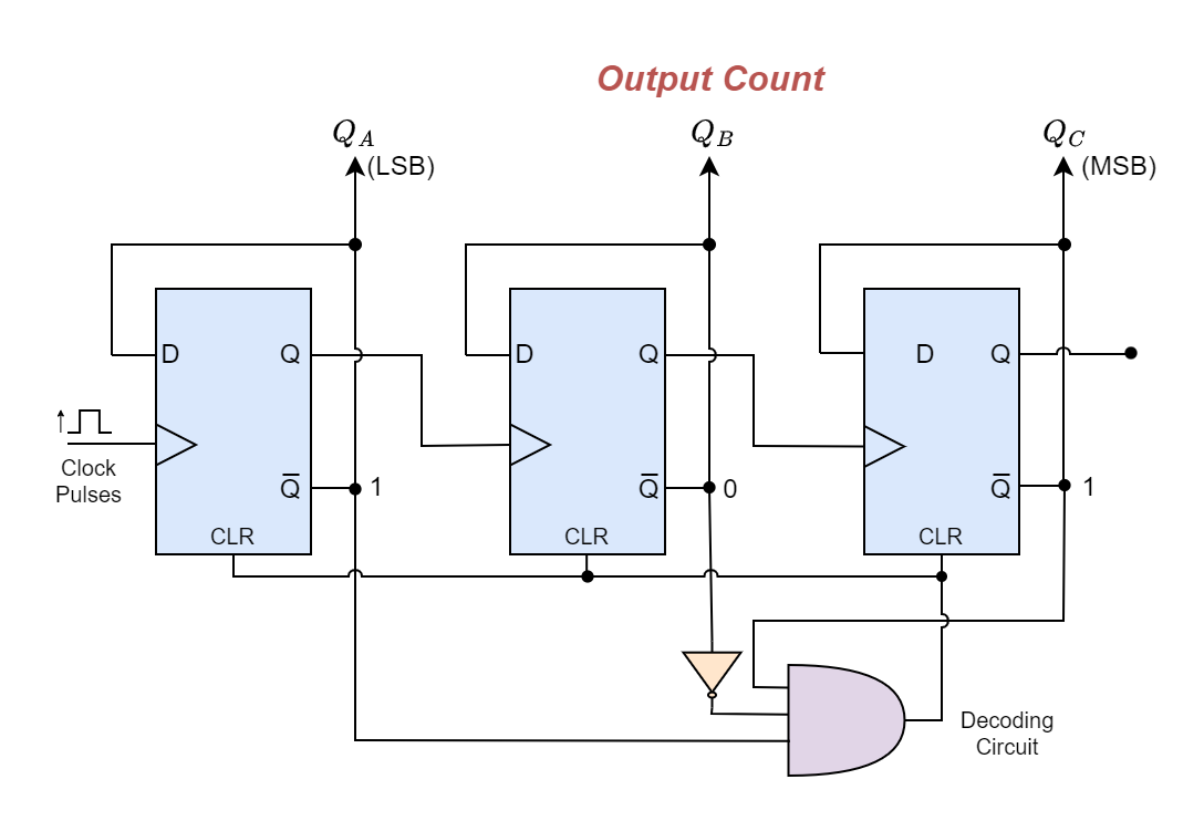
Even though it looks like the counter counts up to the 101 state, the combinational logic decoding circuit will detect this 101 condition when the asynchronous count sequence reaches the next binary state of 101 (5). As a result, the AND gate will generate a logic level “1” (HIGH) output, which will reset the counter back to its initial zero state. As a result, the counter only stays in this momentary condition of 101 for a brief period before resetting to 000.
Consequently, after the AND gate outputs a 5 (decimal) count, we may utilize the input decoding of the AND gate to reset the counter back to zero, providing us with the necessary MOD-5 counter. The counting sequence is unaffected by the decoding circuit’s low (LOW) output.
Modulus 5 Mod Counters and Truth Table
Then, using synchronous or asynchronous combinational logic decoding circuits around a simple counter, we may create whatever kind of MOD Counter we need by decoding each of the counter’s distinct output states, which allows us to reset the counter to the required count.
Any logic circuit may be used to reset the flip-flops at the necessary count, as seen in our straightforward MOD-5 example above, where we decoded the 101 binary output state using a 3-input AND gate.
Asynchronous counters can construct MOD counters of any size with a specified count, but one drawback is that they may cause “glitches,” or unintended consequences when the counter hits its reset condition.
Since the counter’s outputs might change over this small period, it is occasionally preferable to use synchronous counters instead of modulo-m counters since they all change states simultaneously because they are all synchronized by the same clock signal.
Modulus 10 Mod Counters
The Decade Counter is a fine example of a modulo-m counter circuit that creates a counter with a modulus of 10 by utilizing external combinational circuits. Divide-by-10 counters, like the TTL 74LS90, are appropriate for human interface applications that necessitate a digital display since their counting sequence consists of 10 states.
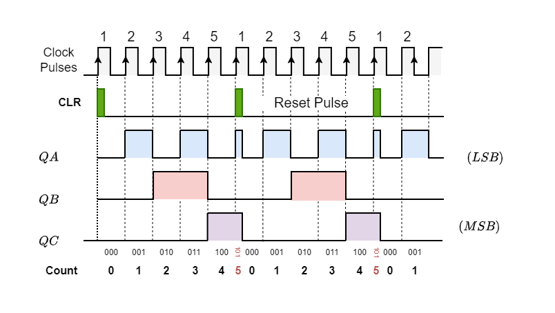
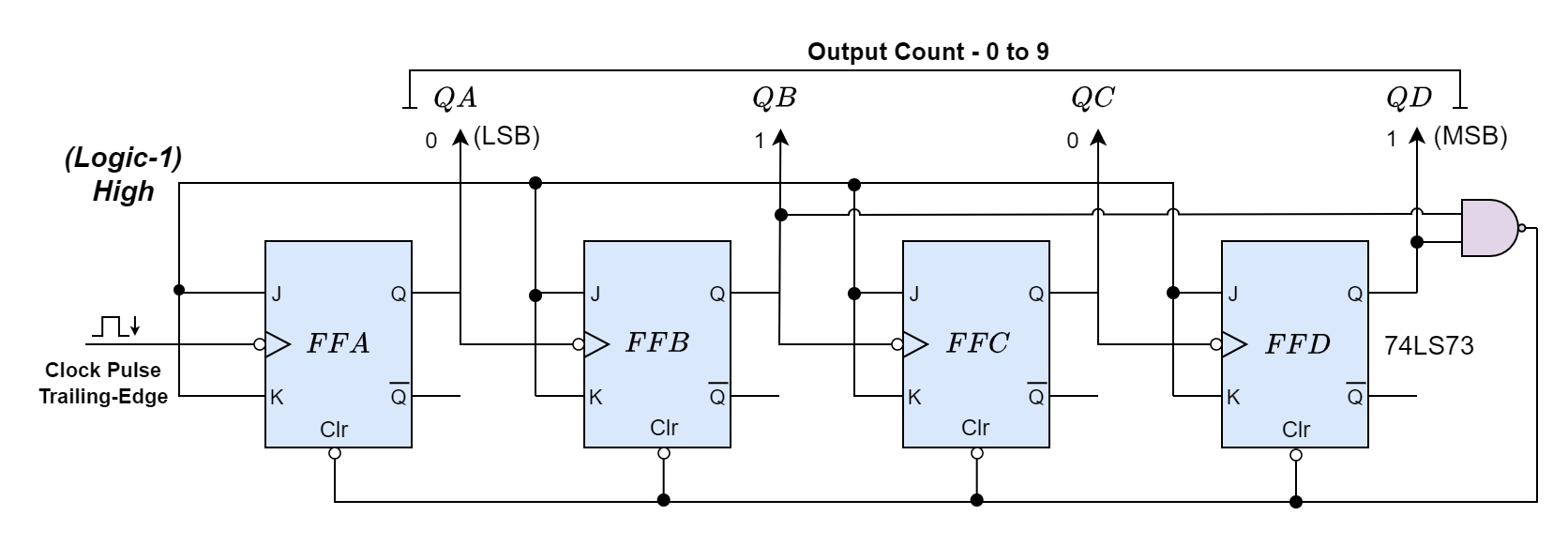
Using external AND and OR gates, we can detect the occurrence of the 9th counting state and reset the decade counter back to zero. The decade counter has four outputs that result in a 4-bit binary value. It counts up from 0 to 9 continuously after receiving an input clock pulse, just as other mod counters.
The counter returns to 0000 instead of incrementing to 1010 when it hits count 9 (1001 in binary). The JK flip-flops (TTL 74LS73), which change states on the negative trailing edge of the clock signal as indicated, can be used to create the basic circuit of a decade counter.
MOD-10 Decade Counter
MOD Counters Summary
- MOD counters are sequential logic circuits that count to a predetermined modulus value before restarting. They can count upwards, downwards, or both, depending on their design, and are triggered by an external clock signal.
- MOD counters are typically constructed using flip-flops, with D-type flip-flops being commonly used due to their simplicity. Flip-flops store binary data and are edge-triggered, changing states based on the clock signal.
- These counters have a modulus value determined by the number of flip-flops. For example, a MOD-4 counter requires two flip-flops and can count through four distinct states (00, 01, 10, 11). Modulus values are powers of two, but custom values (e.g., MOD-5) can be achieved using logic gates.
- A counter’s modulus is expressed as 2n, where n is the number of flip-flops. Thus, a three flip-flop counter, often known as a MOD-8 counter, may count up to 23 = 8 counting states. The counter can count up to two binary numbers, which is 2n–1, for a maximum count of (111)2 = 23–1 = 710. Next, the counter advances by 7 numbers.
- These counters reset after counting up to a specific number less than a power of two (e.g., MOD-5 or MOD-10 counters). They often use external logic gates to detect specific states and reset the count to zero, such as in the case of a decade counter (MOD-10), which resets after reaching 9. Digital display interfaces can benefit from the usage of decade counters. The MOD-6 and MOD-12 counters are additional MOD counters that are used in digital clocks to show the time of day.
Please follow and like us:
Subscribe
Login
0 Comments


