OPAMP Multivibrator
- Boris Poupet
- bpoupet@hotmail.fr
- 7.431 Views
- 2 Comments
Introduction
This tutorial will focus on a configuration commonly known as the multivibrator and particularly on op-amps based circuits. Indeed, multivibrators can also be designed thanks to bipolar transistors or also timer integrated circuits such as NE555 but we will focus on OPAMP implementation.
In its general definition, a multivibrator is an electronic oscillator that generates a non-sinusoidal waveform at its output such as a square or triangular signal for example.
Multivibrators can be differentiated into three categories depending on how they are controlled (the trigger):
- Astable: no triggering
- Monostable: one trigger pulse
- Bistable: two trigger pulses
First of all, we focus on an op-amp based circuit known as the Schmitt Trigger, already briefly presented in the op-amp comparator tutorial. This circuit will indeed enable us to understand the major ideas behind the astable multivibrator.
In the following sections, we focus on the astable, monostable, and bistable op-amp based multivibrator circuits, their properties, and their differences.
Schmitt trigger
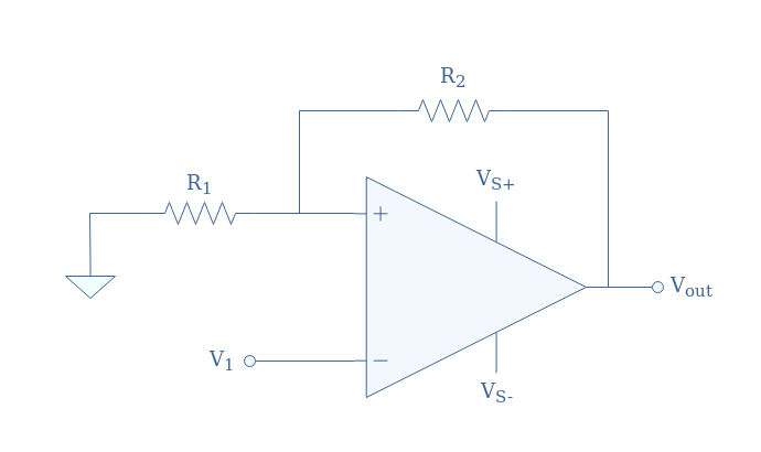
An inverting Schmitt trigger circuit is presented in Figure 1:
The transfer characteristic of this circuit is a hysteresis plot given by the following Figure 2:
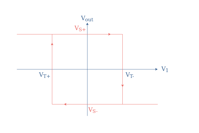
The threshold voltages are always symmetrical (VT-=-VT+) and given by:
- VT+=-VS(R1/(R1+R2))=-βVS
- VT-=+VS(R1/(R1+R2))=+βVS
With β=R1/(R1+R2) known as the feedback fraction provided by the voltage divider circuit. The supplying voltages VS+ and VS- can be assimilated to the saturation voltages of the op-amp.
As we can see from Figure 2, if the input signal V1 reaches or exceeds the threshold voltage VT-, the output will negatively saturate. After that, if the input decreases down to the threshold voltage VT+, the output will switch to its positive saturation level.
As a consequence, for any periodic signal input that is applied to the inverting pin of the op-amp, a rectangular output will be provided by the Schmitt trigger acting as a rectangular converter.
We show in Figure 3 how a sinusoidal waveform would be converted by the Schmitt trigger:
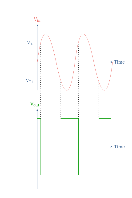
It is interesting to note that the period of the output and input signals match, regardless of the position of the threshold voltages as long the amplitude of the input signal is higher than the threshold value.
Op-amp Astable Multivibrator
An op-amp based astable multivibrator circuit is presented in Figure 4:
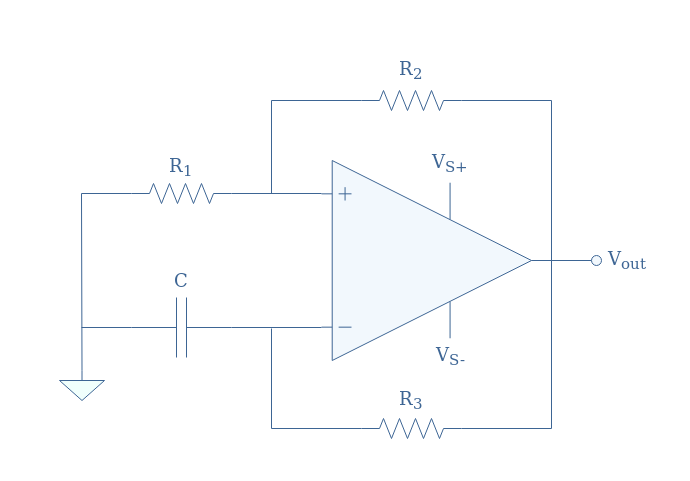
As mentioned in the introduction section, we can see that in this example of an astable multivibrator, no external input signal is present as both inverting and non-inverting pins are indirectly wired to the ground. Instead, as we will detail during this section, the triggering signal will be provided by the charge/discharge cycles of the capacitor present at the inverting input.
The functioning of the astable multivibrator is quite simple, as when V+>V–, the output saturates in positive values and when V+<V–, the output saturates in negative values.
If we set an origin of time where the capacitor is fully discharged, the inequality V+>V– is respected and as long as this condition is valid, the capacitor is charged through the resistor R3. After a certain time, the charge of the capacitor is high enough so that the voltage produced across it exceeds V+, we obtain therefore the inequality V+<V–. Finally, the capacitor begins to discharge until the first inequality is satisfied again, the circuit will continue to oscillate permanently between these two states, thus the label “astable”.
To illustrate this behavior, a chronogram of V– (the capacitor voltage) and Vout is presented in Figure 5:
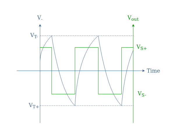
The sawtooth shape for the voltage V– is typical for a capacitor that charges and discharges by following laws of the form:
- V–(t)=VT(1-exp(-t/τ)) for the charge
- V–(t)=VTexp(-t/τ)) for the discharge
With τ being the time constant equals to the product R3×C. It can be demonstrated that the period T for the output signal can be expressed such as:
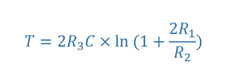
Therefore, we can see that by increasing either the value of R3 or C, the time constant τ is increased, which increases the charge and discharge time of the capacitor and in turn decreases the frequency of the output signal. Moreover, the period can be modified by changing the values of the feedback resistor (R2) and the resistor at the non-inverting input (R1).
Op-amp Monostable Multivibrator
The monostable multivibrator possesses one stable state and one unstable state that can be triggered by an external signal, the period of the unstable state depends mostly on an RC circuit but also on the command.
We present in Figure 6 an op-amp based monostable multivibrator:
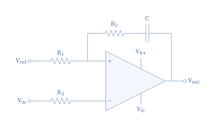
We can already note that this circuit is an inverting comparator as the input is applied to the inverting pin and compared to the reference provided to the non-inverting pin. If Vin<Vref (resp. Vin>Vref), we obtain Vout=Vsat (resp. Vout=-Vsat).
When Vin<Vref, the op-amp saturates in positive values, the voltage across the capacitor (which is fully charged) can therefore be expressed by the difference Vsat-Vref. This state is stable as long as the condition Vin<Vref is satisfied.
In order to induce a change of state for a certain period Tout, the input signal Vin must increase and be higher than the reference value Vref. This can be achieved with an impulsion of period Tin provided to the inverting input such as shown in Figure 7:
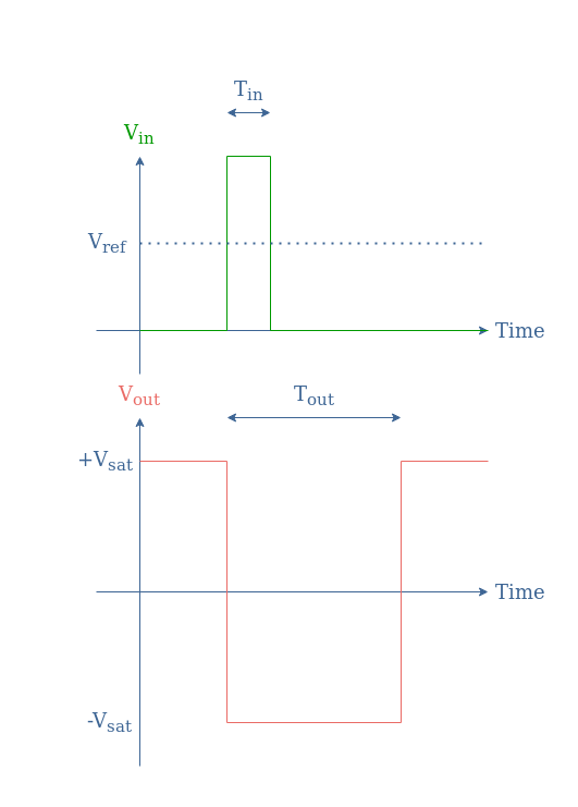
The period Tout for which the system is unstable corresponds to the time constant of the capacitor discharge given by the product R2×C.
Op-amp Bistable Multivibrator
At the last type of multivibrator, the bistable configuration, both states are stable and the transition from one to another requires a different type of trigger.
The circuit of a bistable multivibrator is actually the same as an inverting Schmitt trigger which is already presented in Figure 1.
Before detailing the function of this circuit, we present its corresponding chronogram where we show how the transition between states is triggered:
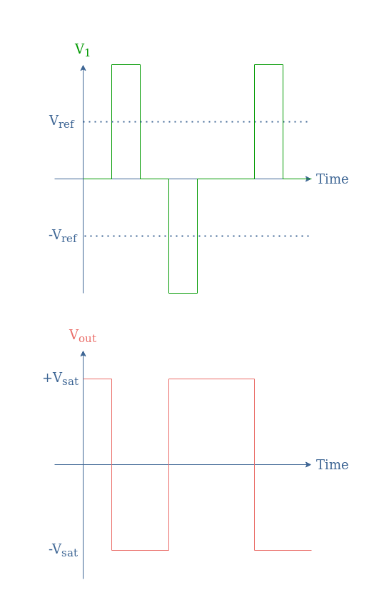
As we can see, the transition from the +Vsat to -Vsat is realized similarly than for the monostable configuration by a positive impulse at the inverting input. The transition back from -Vsat to +Vsat is however not spontaneous as both states are here stable, it requires therefore a negative impulse.
In order for the impulses to effectively trigger the state transition, their absolute value must be higher than a certain reference value (Vref) given by the voltage absolute value at the non-inverting pin βVsat.
To understand the function, we can describe how the circuit behaves depending on the input signal provided:
Before the first input impulse, V1=0 and V+=βVsat, since V+>V1, Vout=+Vsat. When the first positive impulse input is applied, V1>V+ and therefore the output and non-inverting voltage switch both to a low state, respectively Vout=-Vsat and V+=-βVsat. When V1=0 again after the end of the first impulse, the output signal remains at -Vsat because V1>V+. In order to transition back to the initial state, V1 must become lower than V+ which is achieved by a negative impulse of absolute value greater than βVsat.
Conclusion
Multivibrators are simple electronic oscillators that can be used for logical applications (with two states) such as timers or flip-flops. They can be implemented thanks to operationnal amplifiers, and particularly with a comparator-based configuration.
The first section of this tutorial is a reminder for the Schmitt trigger configuration which constitutes the base design for the multivibrators presented in this article. A Schmitt trigger is a simple comparator circuit which output can only be equal to two distinct values and which depends on whether the input provided is higher or lower than a certain reference voltage.
The astable multivibrator is a Schmitt trigger which input branch is a feedback loop with an additional RC series component. No external input is present in this circuit as the discharge/charge cycles of the capacitor provides the necessary trigger signal in order for the output to permanently switch between its high and low states.
For the monostable multivibrator, the reactive component is present in the positive feedback loop of the Schmitt trigger. This particular desgin ensures that one state is stable and the other is unstable as the circuit always tends to come back to its initial state. In our example, the transition from a high to a low level is triggered by an external positive impulse, the period of this unstable state is given by the time constant of the RC series branch.
Finally, the bistable multivibrator is the most basic circuit as it is exactly the same design as a Schmitt trigger. In this case, both low and high states are stable and the transitions are triggered by either positive or negative impulses.


The formula in eq. 1 is wrong, in the natural logarithm, the correct expression is (1 + 2R1/R2)
Thanks for noticing, we fixed it.