Power in AC Circuits
- Boris Poupet
- bpoupet@hotmail.fr
- 4.815 Views
- 0 Comments
Introduction
As a general concept, the power describes the speed at which a certain amount of energy is released/transmitted by a system. This energy can be of different forms: kinetic, magnetic, electric … etc
In any domain, the power is therefore expressed as a quantity of energy per unit of time. The international unit for the power is in Joules/second (J/s) which is also known as Watts (W).
In electricity, the power is determined by the product of the voltage and current signals. The hydraulic analogy is usually used to better understand the concept and draw similarities between the two domains. Indeed, the voltage can be associated with the pressure of a fluid and the current with the movement of the fluid. If any of these values increase (resp. decrease), the power also increases (resp. decreases).
In this tutorial, we will focus on the power in AC circuits, which has a different form than DC circuits. For this reason, in the first section, we discuss how to determine the AC power and where its expression comes from.
The second section will introduce an important concept called the power factor which is crucial to understand the power in AC circuits.
The last section focuses on the power triangle concept, which is associated with some definitions. We will see that power in AC circuits can take three different forms.
Power of a sinusoidal waveform
Consider an electrical AC sinusoidal signal which is characterized by its voltage V(t)=Vmax×sin(ωt+ΦV) and current I(t)=Imax×sin(ωt+ΦI) where Vmax, Imax are the peak values, ω is the common angular pulsation and ΦV, ΦI are the instant phase of each signal. The phase-difference can, therefore, be defined as ΔΦ=ΦV-ΦI.
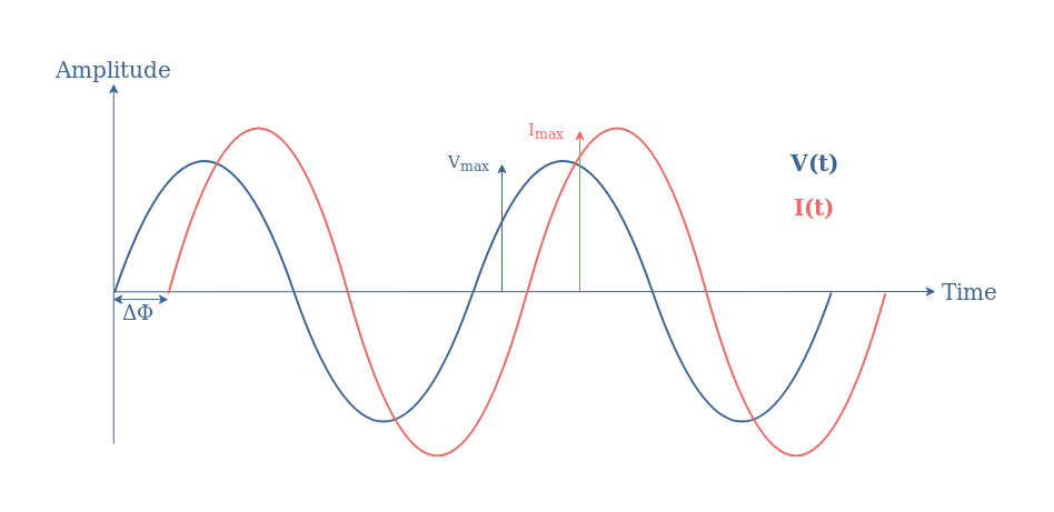
We define the instantaneous power similarly to the DC power by P(t)=V(t)×I(t). When using the expressions of V(t), I(t), the trigonometric formula sin(X)sin(Y)=1/2(cos(X-Y)-cos(X+Y)), and the fact that (Vmax×Imax)/2=Vrms×Irms, it comes:

The first term of this formula is constant and depends only on the phase-shift between the voltage and current, it is known as the active power. The second term is time-varying, it depends on both the angular pulsation and phase-shift.
When taking the average value of P(t) over a period T of the signal, only the active power remains as the average of a time-dependant cosine term is always equal to zero.
Finally, we can say that the power dissipated in an AC circuit is given by the active power which corresponds to the average power:

The term cos(ΔΦ) is known as the power factor, it is a real number between 0 and 1 that reflects how efficiently a component or a circuit consumes the power injected to it. More details about Equation 2 and the power factor are given in the following section.
Power factor
The power factor is often noted λ=cos(ΔΦ), it is equal to the ratio P/S with S=Vrms×Irms being the apparent power, which we focus more in the third section about the power triangle.
It is clear from Equation 2 that the power factor dictates how efficient the power transfer in a circuit is, depending on the phase-shift between the voltage and current. When no phase-shift (ΔΦ) is observed, the circuit or component is said to be purely resistive such as ideals resistor. In this case, the power transmission is maximum and equal to Vrms×Irms.
An example of a purely resistive situation is illustrated in Figure 2 with Vmax=1 V and Imax=2 A:
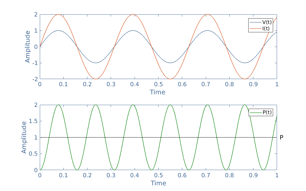
The simultaneous variations of V(t) and I(t) leads to a product P(t) always positive. The average power is therefore strictly positive. Since Vrms=1/√2 and Irms=2/√2, the AC power is given by P=1 W (dark line in Figure 2).
On the other hand, a phase-shift of 90° in absolute value can be observed in purely reactive circuits or components, such as ideal capacitor or inductor. We illustrate this case with the same example as presented previously but this time with λ=0:
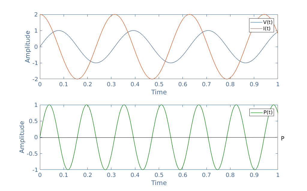
As we can see, due to the phase-shift, the voltage and current signals are not synchronized anymore. The resulting instant power P(t) is a sinewave that alternates between positive and negative values, the average value of the power P is equal to 0 (dark line in Figure 3).
For the intermediate cases 0<λ<1, the AC power is located between 0 and the best case value Vrms×Irms.
Power triangle
In AC regime, we can list three different definitions of power:
- The apparent power is a complex number noted S, its norm equals the product Vrms×Irms and its argument is ΔΦ. It is the power that is “apparently” transmitted into a circuit.
- The active power is a real number and has previously been defined in the first section. It corresponds to the real power that is indeed transmitted into the circuit. Its expression is P=|S|×λ.
- The reactive power is the imaginary part of the apparent power and noted Q. Its expression is given by Q=|S|×sin(ΔΦ).
These different forms of power can be gathered in a complex diagram known as the power triangle:
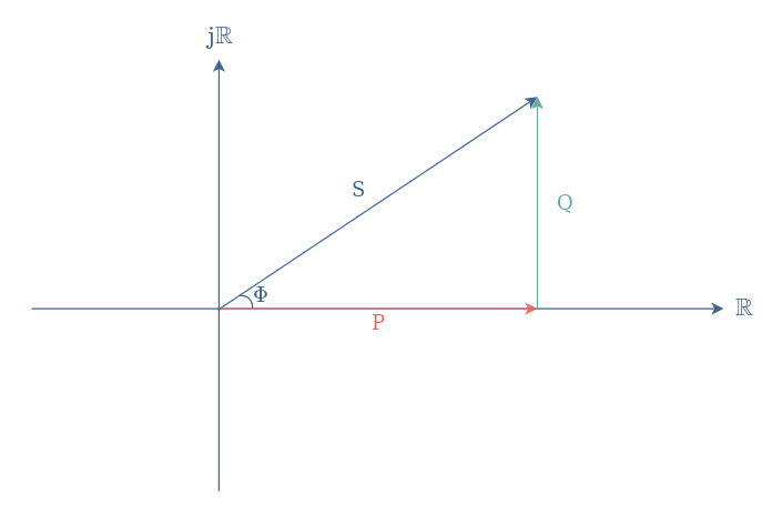
From Figure 4, we can understand that these quantities are linked by the following formula: S=P+jQ.
Even though the reactive power is an imaginary term, it has also a physical meaning. This form of power can be produced by capacitive components or consumed by inductive components.
In many countries, electricity providers bill the reactive power consumers for certain values of λ. This is due to the fact that if a power plant produces for a client a certain apparent power S, but the client only consumes P, the power companies will bill P+Q in order to compensate for the loss in their electric line and encourage the customers to improve their network.
As an example, consider a power plant that needs to provide an active power P to its clients. Client number 1 has an efficient line regarding its reactive power Q1, client number 2 has an inadequate electricity network regarding its reactive power Q2. The apparent power that the electricity company needs to provide is therefore not the same for these different clients:

We can clearly see from Figure 5 that the power that the electricity company needs to generate for client 2 is significantly higher than for client 1 in order for them to be able to use the same final amount P.
Two options are therefore possible for client 2: either he pays a higher bill to the provider or he improves its electricity network. One possible way for client 2 to lower its reactive power down to Q1 is by capacitive compensation.
Indeed, inductive components tend to increase the reactive power (arg(ZL)=+90°) and at the opposite, capacitive components tend to decrease it (arg(ZC=-90°). Choosing an appropriate value of a series capacitor can, therefore, bring back the reactive power Q2 to acceptable levels.
Conclusion
Power in AC circuits cannot only be described by the peak values of the voltage and current waveforms. These signals are indeed not always synchronized because of a phase-difference induced by reactive components. The expression of the power is therefore affected by a term λ called the power factor that depends on the value of the phase-shift.
The power factor can only take a value between 0 and 1, and both of these extrema reflect respectively a purely reactive or resistive behavior of the circuit.
One way to visualize the influence of the power factor is through the concept presented in the last section called the power triangle. The active power effectively consumed by the circuit can indeed be seen as the apparent power (that should have been transmitted) multiplied by a corrective factor. The dual of the active power, which is also the imaginary part of the apparent power is the reactive power and plays an important role for electricity providers that keep track of its value in order to adjust their client’s bill and observe the efficiency of their lines.


