

Simple LED Flasher
- Muhammad Shahid
- m_shahid@live.co.uk
- 15 min
- 75 Views
- 0 Comments
- 4 Likes

Introduction
This simple circuit illuminates an LED or bulb using a ripple counter in a specific order at a predefined interval.
Electronics enthusiasts and students often like building different circuits for their home or school projects, particularly those that flash a few lights. One incredibly flexible integrated circuit (IC) that may be used to create a straightforward LED flasher circuit is known as a binary ripple counter. Several circuits and kits in the market can flash any number of LEDs or lights intermittently, randomly, or consecutively.
As we have discussed in the Counters’ lesson, ripple counters are toggle flip-flops that we can utilize in our basic LED flasher design to act as frequency dividers, dividing the reference clock input by a particular period to produce a new, lower-frequency signal.
Since not every flip-flop in these counters’ “toggles” in unison when an external clock pulse is applied, these counters are termed asynchronous. Typically, the toggling takes place on the clock pulse’s negative edge.
The fundamental feature of all counters is the toggle, also known as a “T-type” flip-flop. Asynchronous counters are also known as “Ripple counters,” because the input clock pulse appears to “Ripple” through the counter when the clock input for one stage is generated from the output of the preceding stage. When each step changes sequentially, the outcome is a ripple effect, which may be effectively used to create a basic LED Flasher circuit.
Ripple counters comprise a series of divide-by-2 T-type flip-flops cascaded together to produce a single divide-by-N frequency divider, where N equals the counter’s bit count. The 74LS93 4-bit (÷16), CMOS 4024 7-bit (÷128), CMOS 4040 12-bit (÷4096), and the bigger CMOS 4060 14-bit (÷16,384) counter are examples of commonly available binary ripple counter integrated circuits.
The “Nth” step of the counter would then be defined as their output count (Qn). Thus, for instance, output Q6 is 26 = 64 (1/64 of the clock frequency), Q12 is 212 = 4096 (1/4096 of the clock frequency), and so on.
The CMOS CD4040B 12-bit Binary Counter is a very versatile integrated circuit that can be used to create a basic LED flasher for use in a variety of different lighting displays. As we’ve seen, there are many binary counters available that can flash any number of lights periodically, randomly, or sequentially.
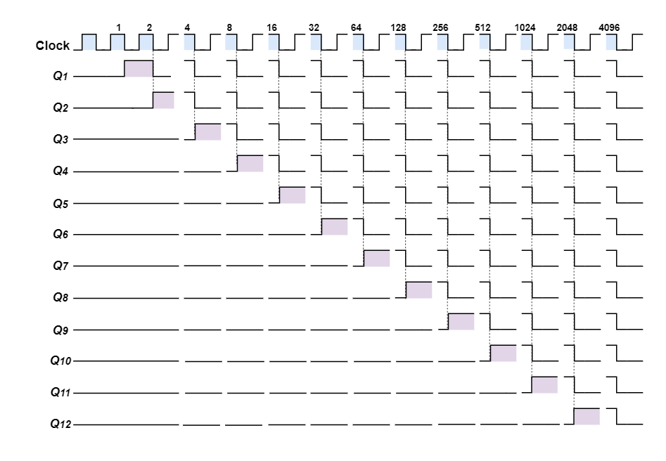
The CD4040B is a 12-bit binary ripple counter that switches quickly and has twelve completely decoded outputs, or a total of twelve different LED sequences. As each clock pulse’s negative edge approaches, these twelve outputs successively switch, creating the binary output sequence seen in the timing diagram.
For a lights project, the 4040 is perfect as a simple LED flasher or lighting display since its outputs alternate between a logic “1” or “HIGH” and a logic “0” or “LOW” on each count, allowing it to create a moving sequence, chaser, or random effect.
Given that the 4040 is a 12-bit ripple counter, the timing diagram that follows illustrates how each of the twelve outputs will alternate between HIGH and LOW in a binary sequence ranging from 0 to 4096 (212).
4040 Ripple Counter Timing Diagram
To include the 4040B ripple counter into our basic LED Flasher circuit, we must first generate a timing signal. A timing or clock signal can be produced in many ways—the possibilities are virtually limitless. However, utilizing a specialized timing integrated circuit (IC) like the NE555 Astable Timer is a very easy and efficient approach to producing a square wave timing signal with the fewest possible components.
The selected input clock frequency determines the timing period T, where T = 1/ƒ. Therefore, our input clock frequency on pin 10 of the 4040 counter would need to be approximately 1kHz, (0.25 x 4096), as shown, if we decide to use the 4040 12-bit (÷4096) counter as part of our simple LED flasher circuit and we want our longest timing period on the 12th-bit to be 4 seconds (2 seconds ON and 2 seconds OFF), or 0.25Hz.
Simple LED Flasher Circuit
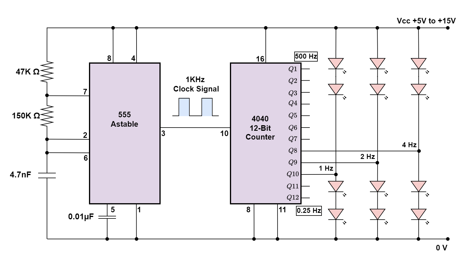
Our simple LED flasher circuit will work best if the LEDs are connected with different outputs since they will flash one at a time, but at separate rates from one another (each output is half the frequency of the preceding one), and they won’t all be “ON” or all “OFF” at the same time.
Depending on which ripple output you connect the LEDs to and how you physically arrange them, you can create any kind of LED flashing light display or a twinkling star effect by using divide-by-2 frequency dividers/counters and multiple LEDs connected to their outputs.
Ripple Counter Output
The outputs of the counters, Q1 through Q12, may either “Source” or “Sink” a load current up to a maximum of around 15mA, which is sufficient for operating the LEDs directly.
Because the 4040 counters can “source” (supply) as well as “sink” (absorb) current, LEDs can be connected between the counter’s output terminal and ground to source load current, or between the counter’s output terminal and supply to sink load current. The illustration for the Sourcing and Sinking is shown in the figure below.
Sinking and Sourcing the Outputs
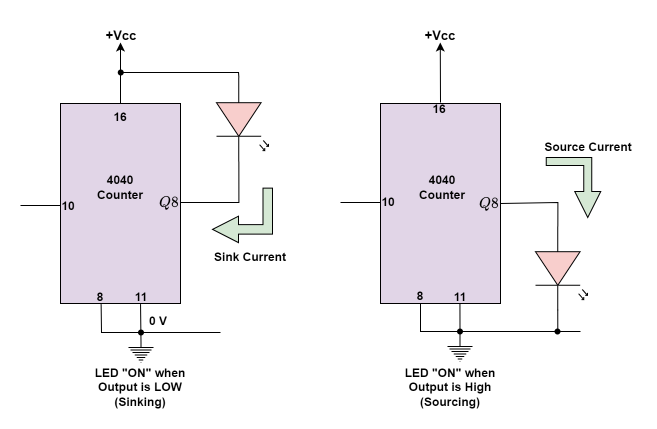
The LED in the first circuit above is linked to the output, in this instance Q8, and the positive supply (+Vcc). This indicates that when the output is “LOW,” the current will “sink” (absorb) or flow into the 4040 counters’ output line, turning on the LED.
The LED is linked between the output, Q8, and ground (0 volts), as the second circuit above demonstrates. This indicates that when the output is “HIGH,” the LED will be “ON” and the current will “Source” (supply) or flow out of the 4040 counters output port.
We can utilize more LEDs in our simple LED flasher circuit because the ripple counter can source and sink its output load current, allowing both LEDs to be connected to a single output terminal. Only one LED will, however, be turned “ON” at any one moment based on whether the output state is “HIGH” or “LOW.”
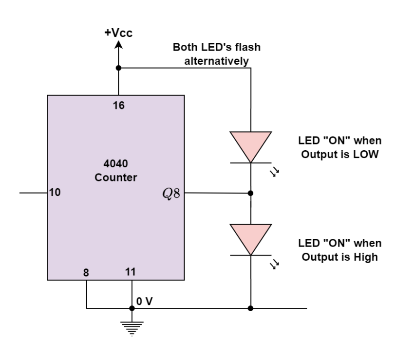
An example of this is shown in the above-shown circuit. Depending on the output, the two LEDs will alternately be turned “ON” and “OFF,” producing an alternating flashing movement. If necessary, series resistors can be added to lower the LED current to less than 15mA.
As we mentioned earlier, the output pins may sink or source the load current up to a maximum of 15 mA, which is more than sufficient to drive or switch LEDs, tiny lights, and other similar devices. However, what if we wished to use this simple LED flasher in place of switching or controlling higher-power equipment like motors, electromagnets, or relays? Then, to supply an adequate current to drive the load, transistors would be required.
Ripple Counter Transistor Driver
If the load current is high, the transistor in the first two cases can be swapped out for a Power MOSFET or a Darlington transistor. It is best to connect a “freewheeling diode” straight across the load terminals of an inductive load, such as a motor, relay, or electromagnet, to absorb any back EMF voltages produced by the inductive device as it changes state.
More LEDs may be added to the output, but they typically need 15 to 20mA at 1.2V to properly glow, when the circuit is connected to a battery or power source. The 4040 IC has the benefit of self-limiting its maximum input/output current, which allows LEDs to be connected directly without the use of current-limiting resistors.
Conclusion
- A simple LED Flasher circuit can be constructed using a binary ripple counter. A binary ripple counter, an integrated circuit (IC), is ideal for this purpose due to its ability to divide frequencies and create sequential outputs.
- Several binary ripple counter ICs are available, such as the 74LS93, CMOS 4024, CMOS 4040, and CMOS 4060, each offering different division capabilities. The CD4040B, a 12-bit binary ripple counter, is highlighted for its versatility in creating LED flashers. It can generate twelve distinct LED sequences, switching outputs with each negative edge of the clock pulse.
- To generate the necessary clock signal for the CD4040B, an NE555 Astable Timer IC is suggested. The timer can produce a square wave timing signal with minimal components. By adjusting the input clock frequency, different flashing rates can be achieved. For example, a 1kHz clock frequency will create a 4-second on/off cycle on the 12th-bit output.
- Transistors or MOSFETs are used to switch higher-power loads, such as motors or relays if needed. Freewheeling diodes are recommended across inductive loads to absorb back-EMF voltages. Additional LEDs can be connected to the outputs, and the 4040 IC’s current-limiting feature allows direct connection without resistors.
Please follow and like us:
Subscribe
Login
0 Comments


