Steady Current And Current Density
- Kamran Jalilinia
- kamran.jalilinia@gmail.com
- 12 min
- 28 Views
- 0 Comments
Introduction
Many practical applications and devices are based on the principles of static electricity. However, electricity was destined to become an inseparable part of our daily lives when scientists learned how to produce a continuous flow of charge for relatively long periods using batteries. The battery, or voltaic cell, was invented in 1800 by Italian physicist Alessandro Volta.
Batteries supply a continuous flow of charge as steady sources of electric current. They allowed scientists to perform experiments to learn how to control the flow of electric charges in circuits. Today, electric currents power our lights, radios, television sets, air conditioners, computers, and refrigerators. They ignite the gasoline in automobile engines, travel through miniature components making up the chips of microcomputers, and perform many more invaluable tasks.
Electric Current
We can imagine an electrical conductor as a repository of free electronic charges that would readily move under the influence of an applied field.
Figure 1(a) shows an isolated copper wire conducting loop. This loop is in electrostatic equilibrium, and no electric field can exist within it or along its surface. Although free electrons are available, no net electric force acts on them, and thus there is no current. Also, all the points of the copper wire are at the same potential.
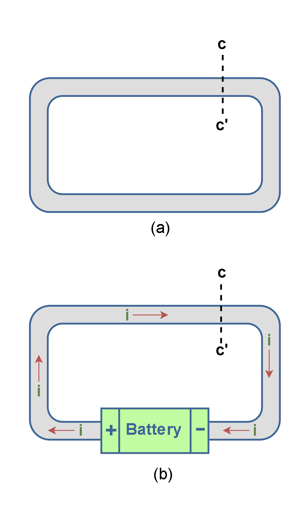
Normally, the free electrons in an isolated length of copper wire are in random motion at very high speeds. If we pass a hypothetical cross-sectional plane through such a wire (like the plane cc’ in Figure 1(a), these electrons pass through it in both directions at the rate of many billions per second—but there is no net transport of charge and thus no current through the wire.
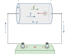
If, as in Figure 1(b), we insert a battery in the loop, the conducting loop is no longer at a single potential. There is an electric potential difference between two ends of the loop that are connected to the positive and negative terminals of the battery. Essentially, this configuration is a closed circuit with a constant voltage source or power supply.
The battery thus produces an electric field within the loop, from the positive terminal to the negative one. The electric field exerts forces on the conduction electrons, causing them to move and thus establishing a stream of electrons. It means that by connecting the ends of the wire to a battery, we slightly bias the flow of electrons in one direction, resulting in a net transport of charge and thus an electric current through the wire.
After a very short time, the electron flow reaches a constant value, and the current does not vary with time. It means the current is in its steady-state condition.
Generally, an electric current is a stream of moving charges. However, not all moving charges constitute an electric current. If there is to be an electric current through a given surface (like the plane cc’ in Figure 1(b), there must be a net flow of charge through that surface.
Figure 2 shows charges moving in a direction perpendicular to a surface of area A. The area could be the cross-sectional area of a wire, for example. The electric current is the rate at which charge flows through this surface.
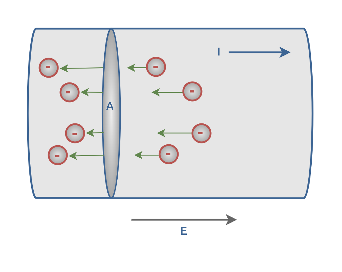
Electric current is symbolized by ‘I’. Suppose ∆Q is the amount of charge that flows through an area A in a time interval ∆t and that the direction of flow is perpendicular to the area. Then the average electric current Iav is equal to the amount of charge divided by the time interval, as explained in Equation 1.

The SI unit for current is the coulomb per second, or the ampere (A). It is named after French mathematician and physicist André-Marie Ampère (1775–1836). Note that one ampere of current is equivalent to one coulomb of charge passing through the cross-sectional area in a time interval of 1 s: 1 ampere = 1 A = 1 coulomb per second = 1 C/s.
Current is composed of individual moving charges, so for an extremely low current, it is conceivable that a single charge could pass through area A in one instant of time and no charge in the next instant. However, practical systems are usually involved with a very large number of charges. Thus, it makes sense to define an instantaneous electric current.
The instantaneous current ‘I’ is the limit of the average current (Iav) as the time interval approaches zero, as explained in Equation 2. It is also commonly denoted by the lowercase letter ‘i’, or expressed as a time-dependent function i(t).

When the current is steady, the average and instantaneous currents are the same (I = Iav) for a period of time.
Figure 3 shows a Longitudinal cut of a conductor with different cross sections (thicknesses) in which current ‘I’ has been established.
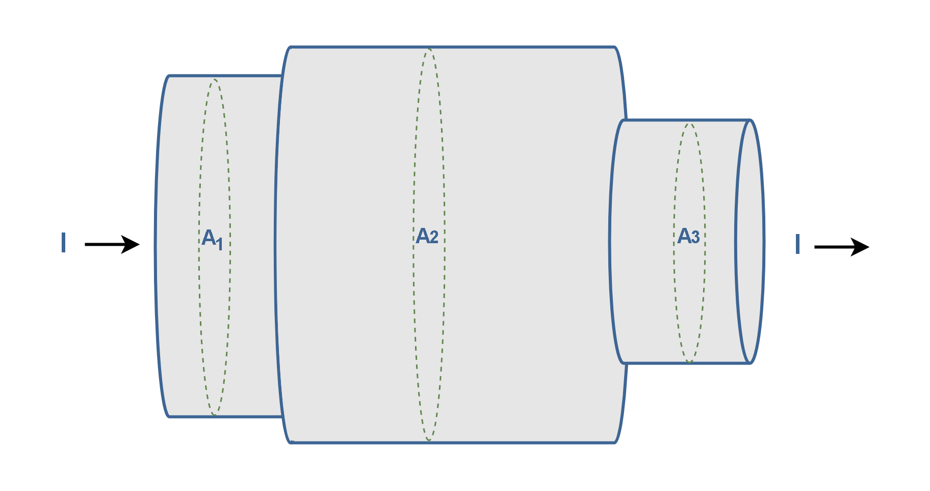
If charge ∆q passes through a hypothetical plane (such as A1) in time ∆t, then the current Iav through that plane is defined as Equation 1.
Under steady-state conditions, the current is the same for planes A1, A2, and A3 and indeed for all planes that pass completely through the conductor, regardless of their location.
Current, as defined by Equation 1, is a scalar because both charge and time are scalars. Yet, as in Figure 1b, we often represent a current with an arrow to indicate that the charge is moving. However, such arrows are not vectors. Current arrows show only a direction (or sense) of flow along a conductor, not a direction in space.
The Directions Of Electric Currents
Moving charges, whether positive or negative, are referred to as charge carriers. In a metal, for example, the charge carriers are electrons. In some cases— for example, gases and electrolytes—the current is the result of the flows of both positive and negative charges, such as ions.
Conventionally, the direction of current is considered as the direction of flow of positive charge from the positive terminal of the source throughout the circuit and into the negative terminal of the source. This historical convention originated about 200 years ago when the ideas of positive and negative charges were introduced. The conventional current direction was established before the discovery of electrons and is still used in circuit analysis.
Essentially, in a common conductor such as copper, the actual direction of current is due to the motion of negatively charged electrons, as shown in Figure 2. However, the conventional direction of the current is opposite the direction of motion of the electrons (see the direction of current I in Figure 2).
The convention in electrical engineering defines positive current as the flow of positive charge from the positive (+) terminal to the negative (-) terminal of voltage sources, such as a battery. For passive devices such as a resistor, capacitor, or inductor, positive current corresponds to the flow of positive charge into the positive voltage terminal of the device. Figure 4 depicts this convention which is universally used in electrical engineering and physics.
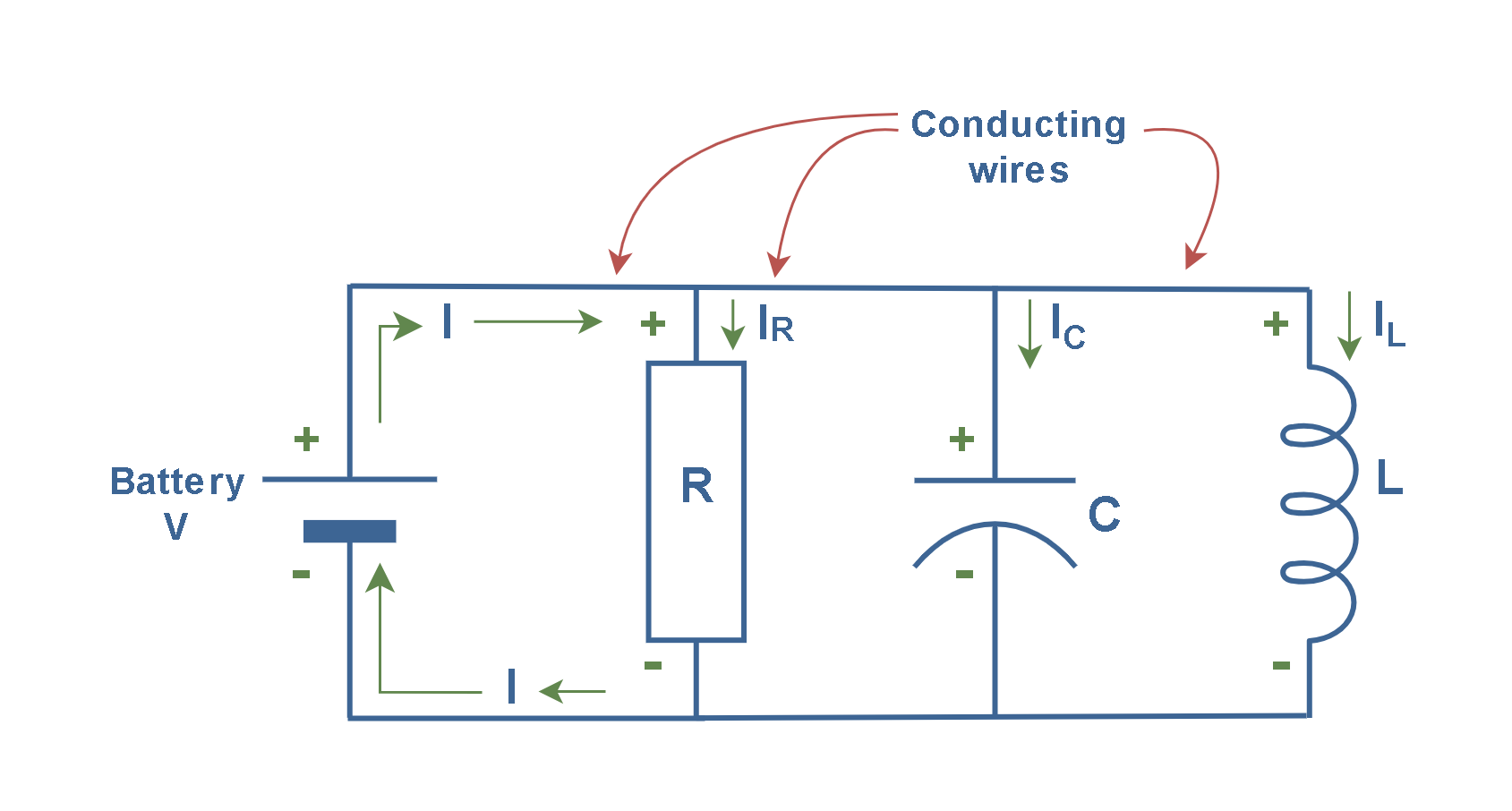
The circuit demonstrates a parallel connection of a resistor (R), capacitor (C), and inductor (L), powered by a battery. This configuration is typical in RLC circuits, which are fundamental in many electronic applications. The conventional current ‘I’ starts from the positive polarity of the battery and continues to move by conducting wires. Then, it is divided between the resistor (IR) and the capacitor (IC) and the inductor (IL). Finally, all portions of the current are joined together to reform the current ‘I’ which returns to the negative polarity of the battery.
Types Of Currents
In practice, we usually deal with two physical mechanisms for current: conduction and convection.
Conduction current consists of the flow of charge carriers (usually electrons) through a conductor in response to an electric field. The electric current mentioned in Figure 1b is a good example of such a case. In some materials, the electric field is also able to dislocate weakly bound electrons from atoms, which then subsequently travel some distance before reassociating with other atoms. For this reason, the individual electrons in a conduction current do not necessarily travel the full distance over which the current is perceived to exist.
Convection current consists of charged particles moving in response to mechanical forces, as opposed to being guided by the electric field. It is usually the flow of electric charge carried by the bulk motion of fluids or gases (like plasmas) containing charged particles. In some systems, it can exist in addition to conduction currents.
An example of a convection current is a cloud bearing free electrons that moves through the atmosphere driven by wind. Other examples of convection currents are ions flow in electrolyte solutions or electron beams in vacuum tubes.
Current Density
From the macroscopic viewpoint, many important problems in electrical engineering concern situations in which the flow of current is not limited in a simple way. Examples include wire- and pin-type interconnects at radio frequencies, circuit board and enclosure grounding, and also physical phenomena such as lightning. To accommodate this more general class of problems, we must define current as a vector quantity. Furthermore, current in these problems can spread out over surfaces and within volumes, so we must also consider spatial distributions of current.
In field theory, we are usually interested in events occurring at a point rather than within a large region, so we find the concept of current density more useful.
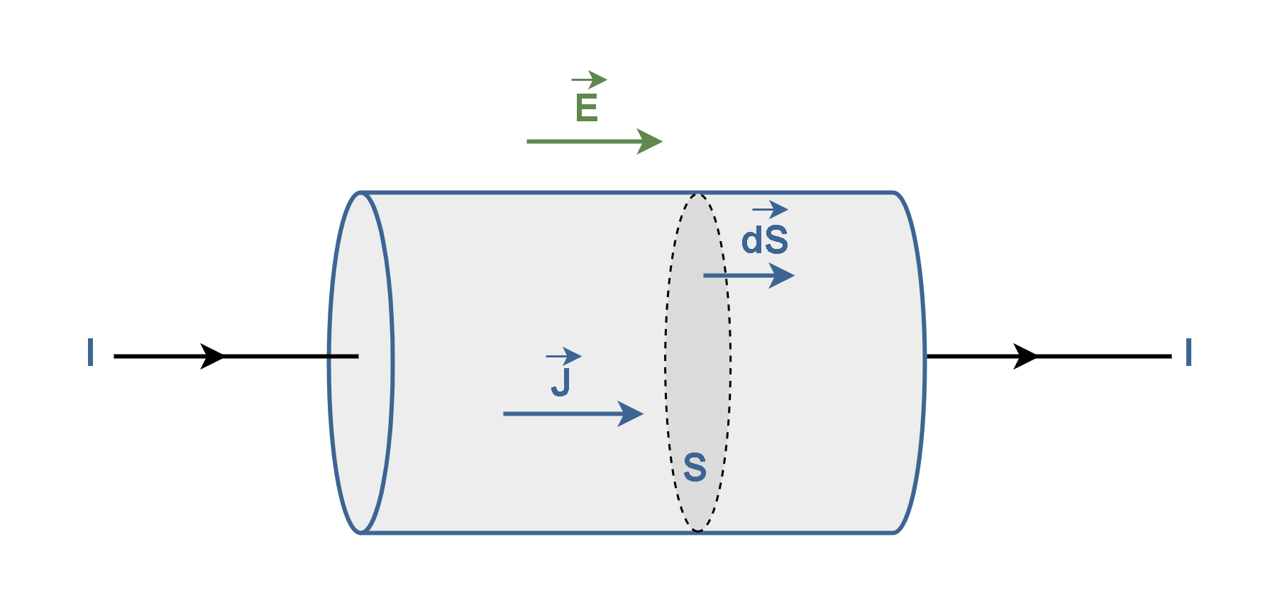
Imagine that electric current I is uniformly distributed within a cylindrical conductor as depicted in Figure 5.

Let ‘J’ be a vector known as current density, representing the quantity of charges flowing across a unit cross-sectional area per second. Also let ‘dS’ be a vector that represents the area of this small surface with the direction normal to the surface.
Then, the total current I passing uniformly through the whole surface ‘S’ is explained by a surface integral in Equation 3.

where dS is measured in units of m2 and J is the surface current density measured in units of amperes per square meter (A/m2), and I is the total current in the units of ampere (A). In other words, the current density J integrated over a surface S yields total current ‘I’ through that surface. In this concept, the field-theory approach may then be related to the circuit approach.
Because of certain symmetries in the structure of the universe, the charge is conservative. This means that the total charge of an isolated system remains the same at all points in time. The Law of ‘Conservation of charge’ is fundamental, strict, and universal.
Thus, if we refer to Figure 3 again, we can conclude that the amount of charge passing through the surfaces A1 or A2 or A3 are constant over the time, i.e., I = constant. However, the current density J does change – it is greater in the narrower conductors with the smaller surfaces (A1 and A3).
Figure 6 shows a conductor with current I0 splitting at junction ‘a’ into two branches with currents I1 and I2.
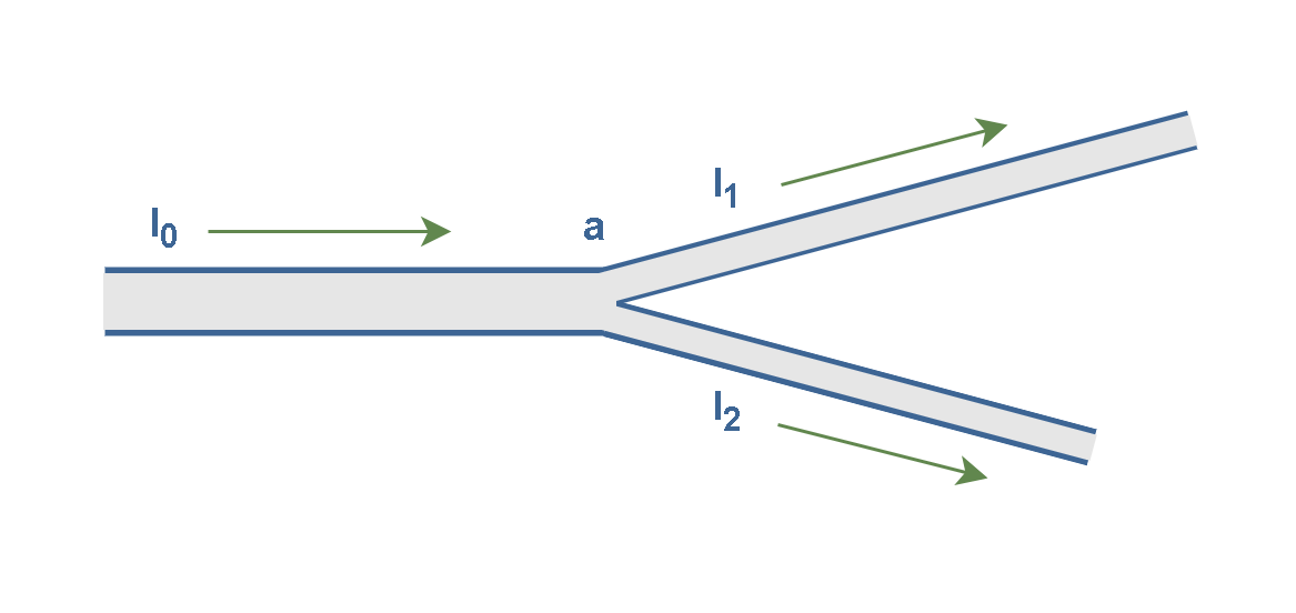
Because charge is conserved, the magnitudes of the currents in the branches must add to yield the magnitude of the current in the original conductor, as Equation 4 explains:

It simply means that the sum of all currents entering a junction (node) must equal the sum of all currents leaving the junction. This principle in circuit theory is known as Kirchhoff’s current law (KCL)—the junction rule.
The relation between currents in Equation 4 is true at junction a no matter what the orientation in space of the three wires. This is because currents are scalars, not vectors.
Drift Velocity
The phenomenon of conduction in a metal can be considered from an atomic or microscopic viewpoint. For our purposes, a simple physical model will suffice. We may think of a conductor as composed of a lattice of fixed positive ions containing an electron gas free to move around. Ordinarily, these free electrons are in a state of random motion due to their thermal energy.
When a conductor does not have a current through it, its conduction electrons move randomly, with no specific direction. However, an applied electric field in the conductor causes the electrons to drift in a specified direction.
Thus, when a conductor has a current passing through it, these free electrons still move randomly, but now they tend to drift with a drift velocity vd in the direction opposite to the applied electric field that causes the current. Free electrons moving in a conductor make many collisions with other electrons and atoms. The path of one electron is shown in Figure 7.
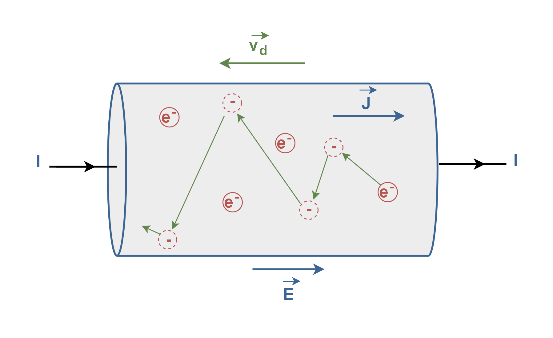
Essentially, the drift velocity is the average velocity of the free charges. Figure 7 relates the drift speed ‘vd‘ of the conduction electrons in a current ‘I’ through a wire to the magnitude ‘J‘ of the current density in the wire. It also shows the drift of negative charge carriers in the opposite direction of the applied electric field ‘E’.
let us assume that these charge carriers all move with the same drift speed vd and that the current density J is uniform across the wire’s cross-sectional area ‘S’. Then, the current density can be calculated as Equation 5.

where ‘n’ is the number of charge carriers per unit volume and ‘e’ is the charge of one electron in terms of coulombs.
The product ‘ne’, whose SI unit is coulomb per cubic meter (C/m3) is the charge carrier density. For positive carriers, vectors J and vd have the same direction. For negative carriers, vectors J and vd have opposite directions.
When charged particles are forced into this volume of a conductor, an equal number of charges are quickly forced to leave. The repulsion between like charges makes it difficult to increase the number of charges in a volume. Thus, as one charge enters, another one leaves almost immediately, carrying the signal rapidly forward.
The drift speed is tiny compared with the random-motion speeds, which are typically around 106 meters per second (m/s). For example, in the copper conductors of household wiring, electron drift speeds are perhaps 10-5 to 10-4 m/s.
Drift velocity is quite small since there are so many free charges. If we have an estimate of the density of free electrons in a conductor, we can calculate the drift velocity for a given current. The larger the density, the lower the velocity required for a given current.
Summary
- Electric charges in motion constitute an electric current.
- The flow of electric charge through a conductor is an example of current.
- The SI unit of current is coulomb per second (C/s), or the ampere (A).
- A current of 1 A is produced by a charge flowing past a fixed point at the rate of 1 C/s.
- The direction of conventional current is the direction of positive charge flow, even if the actual charge carriers are negative and move in the opposite direction.
- Despite being opposite to electron flow in metals, using conventional current direction leads to correct results in circuit analysis.
- Conduction current is the flow of charge in response to an electric field.
- Convection current is the movement of charged particles due to mechanical forces.
- Current density is defined as the current passing through a small planar surface within a volume.
- Current density is a vector represented by J and measured in amperes per square meter (A/m²).
- Steady currents have constant magnitude over time.
- The average current is the average of instantaneous currents over a period of time.
- The total current into a junction must equal the total current out of the junction (Kirchhoff’s Current Law).
- In conducting materials, electrons are loosely bound and can migrate readily from atom to atom.
- The average velocity of free charges is called the drift velocity and it is in the direction opposite to the electric field for electrons.
More tutorials in Electromagnetism
- Electric Conductivity, Resistance and Ohm’s Law
- Steady Current And Current Density
- Electric Displacement and Electrostatic Energy
- Electrostatic Fields In Material Bodies
- The Electric Flux And Gauss’s Law
- Electric Potential In Uniform Fields
- Electric Potential In Nonuniform Fields
- The Electric Field
- The Electric Force


