
Synchronous Counter
- Muhammad Shahid
- m_shahid@live.co.uk
- 12 min
- 237 Views
- 0 Comments
- 4 Likes

Introduction
The name “Synchronous Counter” comes from the fact that all the flip-flops inside the counter are driven through a single clock source and because of this parallel clock sourcing arrangement of flip-flops in a synchronous counter, they are often referred to as “Parallel Counters”. This indicates that with each clock pulse, the counter’s output varies concurrently and reliably. In addition to having shorter propagation latency and power usage than asynchronous counters, synchronous counters are simpler to build and evaluate. Nevertheless, they also need more wires and logic gates, which raises the circuit’s potential cost and complexity.
Synchronous counters can be built with Toggle or D-type flip-flops. In contrast to asynchronous counters, which have a direct connection between the output of the preceding stage and the clock input of the next counter stage in the chain, the synchronous counter has synchronized timing for each level. Therefore, the overall operation is faster in synchronous counters compared to asynchronous ones.
The issue with asynchronous counters is that they experience a phenomenon called “Propagation Delay,” whereby the timing signal has a slight delay as it passes through each flip-flop. On the other hand, the external clock signal is connected to the clock input of each flip-flop within the synchronous counter. This results in all the flip-flops being synchronously timed (in parallel) with each other, providing a fixed time correlation. Stated differently, the output is “synchronized” with the clock signal as it varies.
As a result of this synchronization, there is no propagation delay since every single output bit changes its state in response to the common clock signal at precisely the same moment.
Binary 4-bit Synchronous Up Counter
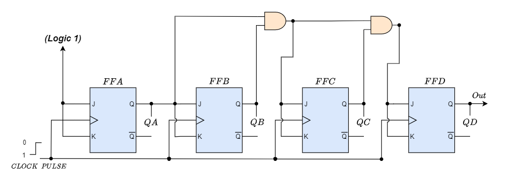
As shown in the picture above, the JK flip-flops in the counter chain are fed by the same external clock pulses, which are meant to be counted. The J and K inputs are connected in toggle mode, but only the flip-flop FFA (LSB), which is the first flip-flop, has HIGH logic (1) connected to it, allowing it to toggle on every clock pulse. Afterward, in reaction to the common clock signal, the synchronous counter advances one state for every pulse in a predefined sequence.
The J and K inputs of flip-flop FFB are directly linked to the output “QA” of flip-flop FFA, while the J and K inputs of flip-flops FFC and FFD are driven by independent AND gates that are additionally provided with signals from the input and output of the preceding stage. The necessary logic for the JK inputs of the subsequent level is produced by these extra AND gates.
The same counting sequence as with the asynchronous circuit may be obtained if we enable each JK flip-flop to toggle depending on whether all previous flip-flops’ outputs (Q) are “HIGH.” This eliminates the ripple effect because every flip-flop in this circuit will be timed at precisely the same time.
Since all the counter stages are triggered simultaneously in parallel, synchronous counters do not have an intrinsic propagation delay, hence their maximum operating frequency is significantly higher than that of an equivalent asynchronous counter circuit.
4-bit Synchronous Counter Waveform Timing Diagram

The outputs of this 4-bit synchronous counter count upward from 0 (0000) to 15 (1111) because it counts consecutively on each clock pulse. As such, such kind of counter is also termed as a 4-bit Synchronous Up Counter.
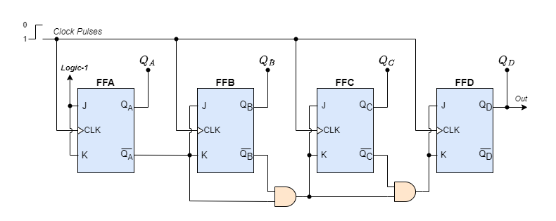
On the other hand, by connecting the AND gates to the flip-flops’ Q̅ output as demonstrated, we can quickly build a 4-bit Synchronous Down Counter and create a timing diagram that is the opposite of the one above. In this case, the counter begins with all its outputs HIGH (1111) and counts down to zero (0000) with each clock pulse application before repeating the sequence.
Binary 4-bit Synchronous Down Counter
Since synchronous counters are made by joining flip-flops together, any number of flip-flops can be joined or “cascaded” together to create a binary counter that is “divide-by-n.” The modulo, or “MOD,” number remains the same as it does for asynchronous counters, allowing truncated sequences to be built alongside a Decade counter or BCD counter that has counts ranging from 0 to 2n-1. Adding an extra flip-flop and AND-gate across up or down the synchronous counter is required to enhance its MOD count.
4-bit Synchronous Decade Counter
Synchronous binary counters may also be used to construct a 4-bit decade synchronous counter, which will provide a count sequence from 0 to 9. With the help of extra circuitry, a regular binary counter may be transformed into a decade (decimal 10) counter to achieve the necessary state sequence. The counter resets to “0000” whenever it reaches the number “1001”. We now have a Modulo-10 counter or decade.
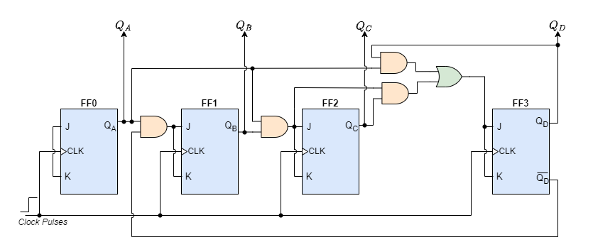
When the counting sequence hits “1001” (Binary 9), which is detected by the extra AND gates, flip-flop FF3 toggles on the subsequent clock pulse. Flip-flop (FF0) toggles on and off with each clock pulse. As a result, the count restarts at”0000,” creating a synchronous decade counter.
The extra AND gates in the counter circuit above can be readily rearranged to generate other count numbers. For example, a Mod-12 counter counts 12 states from “0000” to “1011” (0 to 11) and then repeats, making it appropriate for clocks and other applications.
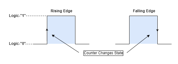
Triggering The Counter
Synchronous counters employ edge-triggered flip-flops, which produce a single count when the clock input switches states on either the “positive edge” (rising edge) or the “negative edge” (falling edge) of the clock pulse on the control input.
Synchronous counters typically count on the rising edge of the clock signal, which is the transition from low to high, whereas asynchronous ripple counters count on the falling edge, which is the transition from high to low.
The most significant bit (MSB) of one counter can control the clock input of the next stage flip-flop, which makes it easier to link counters together even if it may seem strange since ripple counters utilize the clock cycle’s “falling edge” to change states.
This can function because a carry to the next bit must happen at the time when the preceding bit goes from high to low. To connect counters without causing any propagation delays, synchronous counters often have a carry-out and a carry-in pin.
Applications of Synchronous Counters
Digital circuits used in embedded systems, automotive systems, and consumer electronics are all built with synchronous counters. They have precise timekeeping capabilities and drive time displays in forms like hours, minutes, and seconds.
In Arithmetic Logic Units (ALUs), synchronous counters are employed to carry out addition, subtraction, multiplication, and division operations on binary integers. In computation-intensive applications and digital signal processing, they help to efficiently implement digital arithmetic algorithms.
In digital systems, synchronous counters are essentially required for producing accurate timing signals and managing the order of processes. They are utilized in timing generators to produce clock signals with precise frequencies and duty cycles, as well as in synchronization circuits to guarantee synchronized activities among various system components.
They are useful in industrial automation operations, where synchronous counters are used in situations where precise counting of events or occurrences is required. This might include keeping track of the frequency of transmissions in communication systems or counting the pulses in sensor systems.
Advantages:
- The Synchronous counter operates faster as they are not accompanying any propagation delay.
- Error probabilities decreased because logic gates regulate the count sequence.
- synchronous counters are more suitable for high-speed and accurate operations, such as frequency division, binary arithmetic, and digital clocks.
- Synchronous counters can easily be modified and extended to create different types of counters, such as up-down, modulo-n, and ring counters.
Disadvantages:
- The circuit gets increasingly complex as the number of states rises.
- An asynchronous counter has a single common clock pulse that drives all its flip-flops.
- When compared to asynchronous counters, they require more hardware and components.
- Synchronous counters can consume more power than asynchronous counters since they have more logic gates and wiring that draw current.
Conclusion
- Synchronous counters operate using a single clock signal to drive all flip-flops within the counter, simultaneously. This ensures that all the outputs are synchronized with the clock signal, eliminating propagation delays present in asynchronous counters.
- D-type or Toggle flip-flops can be used to create synchronous counters.
- Synchronous counters can be used for the construction of modular counters, including decade counters that count from 0 to 9. These counters reset after reaching the maximum count, achieved through additional circuitry.
- Logic gates are used to regulate the count sequence.
- Compared to asynchronous counters, synchronous counters are simpler to construct.
- It is possible to get an overall speedier operation as compared to asynchronous counters.
- Synchronous counters are more suitable for high-speed and accurate operations, such as frequency division, binary arithmetic, and digital clocks.
Please follow and like us:
Subscribe
Login
0 Comments


