OPAMP Differentiator
- Boris Poupet
- bpoupet@hotmail.fr
- 6.659 Views
- 0 Comments
Introduction
In our previous article about the Integrator op-amp, we have seen that the implementation of a reactive component significantly changes the electrical behavior of OPAMPs in comparison to fully-based resistive designs. Indeed, the presence of a capacitor in the feedback loop constitutes the main aspect of integrators, which perform electrically the mathematical operation of integration.
When the position of the capacitor is inversed, that is to say, that the feedback branch becomes resistive and the input branch reactive, a new configuration commonly known as a differentiator emerges.
The goal of the first section will be to present the general function of the differentiator op-amp and we will of course also demonstrate and explain its output formula.
Such as we have seen for the integrator, the ideal differentiator configuration that we focus on in the first section presents limitations that can be overcome with an alternative design. This limitation and it’s solution are both focused on the second section of this tutorial.
Presentation
The ideal differentiator
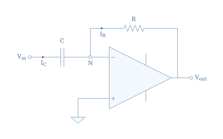
A differentiator is an inverting op-amp configuration in which a capacitor is present in the input branch such as shown in Figure 1 below:
We remind, as we properly explained in the integrator tutorial, that in the DC regime, a capacitor is equivalent to an open circuit while in the high-frequency regime it tends to be a short circuit as the frequency increases.
If we project this observation to the circuit shown in Figure 1, two different configurations can explain the behavior of the differentiator in low and high-frequency regimes:
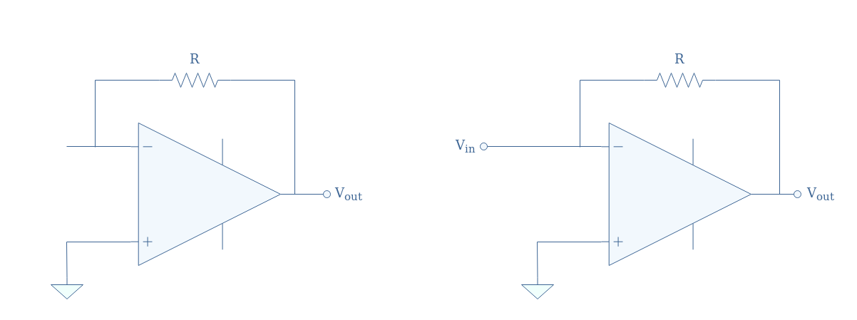
In both cases, the differentiator can be reduced to an inverting op-amp and when the input signal frequency is very low the capacitor tends to block it. On the other hand, when the input signal frequency is high, it is directly supplied to the inverting op-amp input without any intermediary impedance.
In other words, slow variations present in the input signal are not being amplified by this configuration, fast variations are however amplified and affect the output signal.
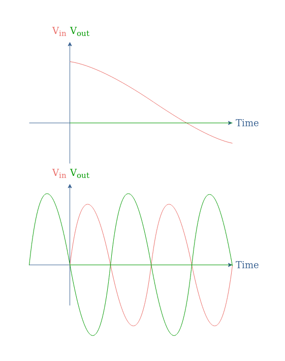
We can highlight that in the second Figure, the output signal is in phase opposition with the input signal.
Output formula
If we suppose the internal op-amp impedance to be very high or tending to infinity in the ideal case, the equality IC=IR is established. If we label this current “I”, it satisfies the input branch in the relation I=C(dVin/dt), moreover, the Ohm’s law in the feedback loop gives Vout=-RI.
Therefore, the output relation of the differentiator is given by Equation 1 below:
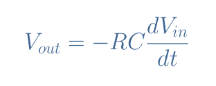
Using the complex notation, Equation 1 can be simplified to Equation 2, which also gives the transfer function T:

These formulas clearly highlight the fact that the differentiator configuration performs the differentiation operation between the input and output.
AC Analysis
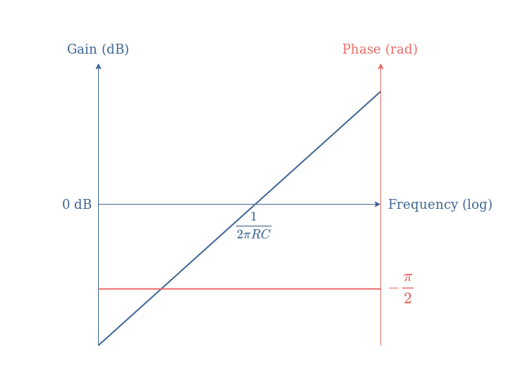
From Equation 2, it is easy to establish that the gain in dB of the ideal differentiator is given by +20log(x), moreover, the phase of a pure negative imaginary number is -π/2 rad.
From this information, the Bode plots of the ideal differentiator are given in the following Figure 4:
The real differentiator
Limitations of the ideal configuration
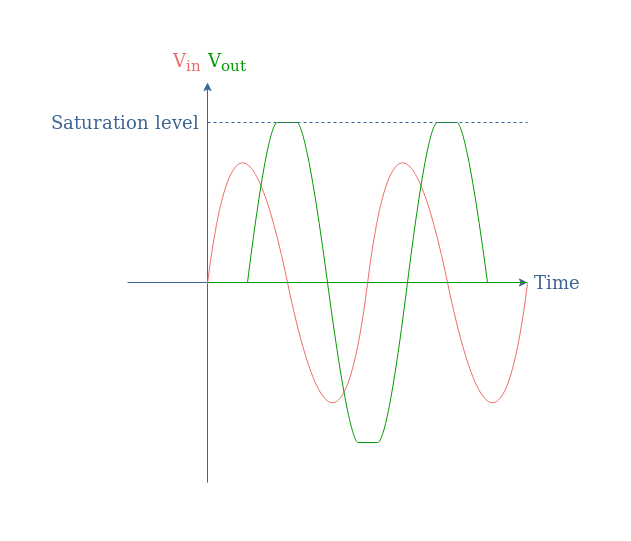
A major gain limitation arises from the ideal configuration. As we have seen in Figure 2, when the frequency increases, the circuit tends towards an inverting configuration with a gain given by -R/Rin (refer to the inverting op-amp tutorial). However, since the input is shortened when the frequency increases, Rin=0,the gain tends to infinite values.
In practice, when the frequency of the input increases too much, a saturation will start to appear which limits the differentiation operation:
Pseudo-differentiator with a series resistor
An improvement that can be made to the differentiator is to place a series resistor in the input branch. This configuration is referred to as a pseudo-differentiator SR (for series resistor).
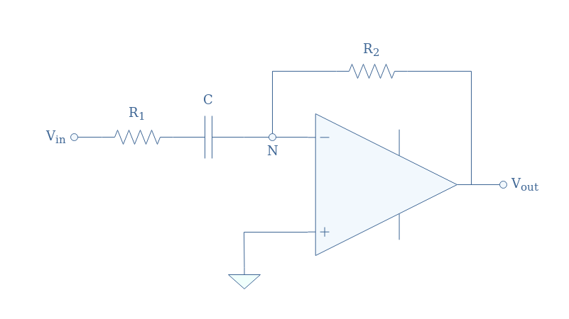
The equivalent circuit for high frequencies will be an inverting op-amp with a finite gain -R2/R1. As a consequence, in the high-frequency regime, when the capacitor impedance tends to zero, the gain will therefore be limited to R2/R1 instead of ∞ which would make the output to saturate as pinpointed in the ideal circuit section.
We can apply Millman’s theorem at the node N in order to analyze this circuit:
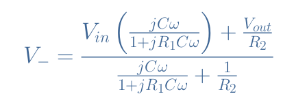
With the virtual earth hypothesis V–=0, we establish the transfer function T of the circuit in Figure 6:

For frequencies from DC up to the cutoff frequency 1/(2πR1C), the transfer function can be approximated to -jR2Cω, which is a similar form of the ideal differentiator transfer function. When the frequency increases and tends to infinite values, a good approximation of the transfer function becomes -R2/R1 which establishes a plateau for the gain.
From these observations, the asymptotic gain Bode plot is given in Figure 7 below, which is typical of a high-pass filter:
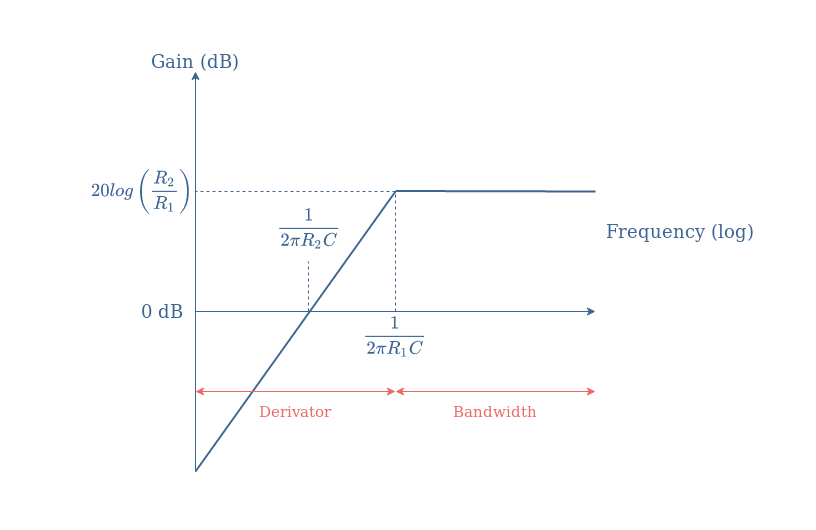
We can conclude by saying that the pseudo-differentiator SR is a good approximation of the ideal differentiator up to the cutoff frequency of the circuit determined by the value of R1 and the capacitor C.
Pseudo-differentiator with a parallel capacitor
Another possible modification that can be applied to the ideal differentiator is to place a capacitor in parallel with the resistor in the feedback loop. The circuit presented in Figure 8 will be referred to as pseudo-differentiator PC (for parallel capacitor).
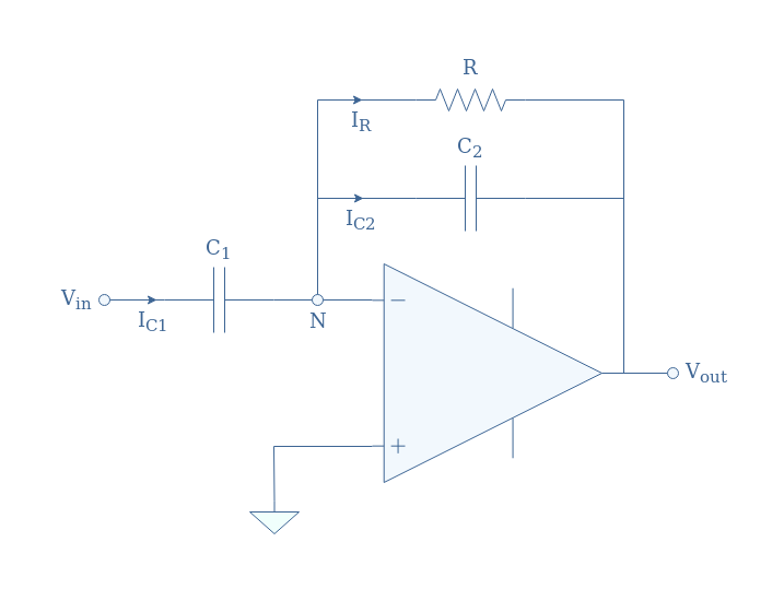
Thanks to the capacitor C2, the equivalent circuit in the high-frequency regime is an inverting voltage buffer which means that the gain will be limited to the unity.
Let’s again apply Millman’s theorem at the node N:

With the hypothesis of the virtual earth, the transfer function T of the pseudo-differentiator PC becomes:

For frequencies from DC up to the cutoff frequency 1/(2πRC2), the transfer function can be approximated to -jRC1ω, which is a similar form of the ideal differentiator transfer function. When the frequency increases and tends to infinite values, the gain of the transfer function reaches a plateau of absolute value 0 dB.
The transfer function of the pseudo-differentiator PC is again equivalent to a first-order high-pass filter such as we show in the following asymptotic Bode plot:
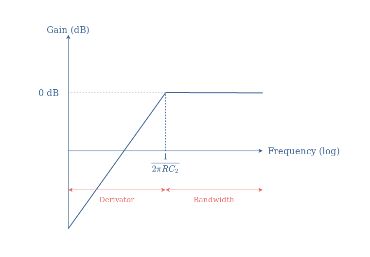
We can conclude by saying that the pseudo-differentiator PC is a good approximation of the ideal differentiator up to the cutoff frequency of the circuit determined by the value of R and the capacitor C2.
Conclusion
The mathematical operation “differentiation” can be realized by an electronic circuit called a differentiator, which is based on an operational amplifier working in inverting configuration with a reactive component in its input branch.
In the first section, we present the ideal differentiator which is a simple circuit to theoretically establish how a differentiator works. In particular, we pinpoint that due to the capacitor in the input branch, the circuit is equivalent to an inverting op-amp with a gain of 0 at low-frequency and a gain tending to infinite values in high-frequency regime.
The consequence of this electrical behavior is that an ideal differentiator can be characterized by a simple transfer function T=+jx, which means that its related Bode diagram is a linear plot with a slope of +20 dB/decade.
However, the ideal differentiator cannot be designed in practice due to the infinite gain the circuit is supposed to have when increasing the frequency. As a consequence, the differentiation operation is limited up to a certain frequency when the output will start to saturate.
Real circuits present either a series resistor in the input branch or a parallel capacitor in the feedback loop in order to limit the gain. “Pseudo-differentiators” as they are called are a good approximation of the ideal differentiator for a certain range of frequency that is determined by the value of their resistive and reactive components.


