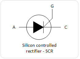
In this article we will discuss about the various types of thyristors. Thyristors are 2 pin to 4 pin semiconductor devices that act like switches. For example a 2 pin thyristor only conducts when the voltage across its pins exceeds the breakdown voltage of the device. For a 3 pin thyristor the current path is controlled by the third pin and when a voltage or current is applied to this pin the thyristor conducts. In contrast to trasistors, thyristors only work on ON and OFF states and there is no partial conduction state between these two states. Basic types of thyristors are: SCR, SCS, Triac, Four-layer diode and Diac.
Silicon Controlled Rectifier (SCR)
Silicon controlled rectifier is normally in OFF state but when a small current enters its gate G it goes to ON state. If the gate current is removed the SCR remains in ON state and to turn it of the anode to cathode current must be removed or the anode must be set to a negative voltage in relation to cathode. The current only flows in one direction from anode to cathode. SCRs are used in switching circuits, phase control circuits, inverting circuits etc.
Silicon Controlled Switch (SCS)
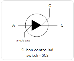
Working of SCS is similar to SCR but also it can be turned off by applying a positive pulse on the anode gate. The SCS can also turned ON by applying a negative pulse on anode gate. The current flows only from anode to cathode. SCS are used in counters, lamp drivers, logic circuits etc.
Triac
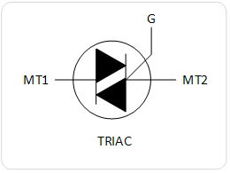
Triac is similar to SCR but it conducts in both directions, means that it can switch AC and DC currents. The triac remain in ON state only when there is current in gate G and switched OFF when this current is removed. Current is flowing in both directions between MT1 and MT2.
Four layer diode
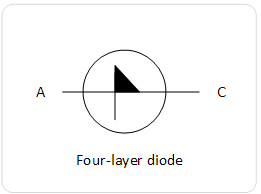
Four layer diode has 2 pins and works like a voltage-sensitive switch. When the voltage between the two pins exceeds the breakdown voltage it turns ON, otherwise it’s OFF. Current flows from anode to cathode.
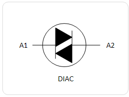
Diac
Diac is similar to four-layer diode but it can conduct in both directions meaning it can contact both AC and DC currents.
Basic SCR Applications
Basic Latching Circuit
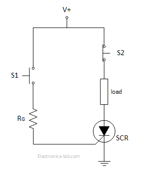
In this circuit a SCR is used to form a basic latching circuit. S1 is a normally open switch and S2 is a normally close switch. When S1 is pushed momentary a small current goes into the gate of SCR and turning it ON, thus powering the load. To turn it off we have to push the S2 push-button so the current through SCR stops. Resistor RG is used to set the gate voltage of SCR.
Power Control Circuit
In this circuit a SCR is used to modify a sinusoidal signal so that the load receives less power than of what would receive if source voltage was applied directly. The sinusoidal signal is applied to the gate of SCR via R1. When the voltage on the gate exceeds the trigger voltage of SCR, it goes to ON state and Vs is applied to the load. During the negative portion of the sine wave the SCR is in OFF state. Increasing R1 has the effect of decreasing the voltage applied to the gate of SCR and thus creating a lag in the conduction time. In this was the load is receiving power for less time and thus the average power to load is lower.
DC motor Speed Controller
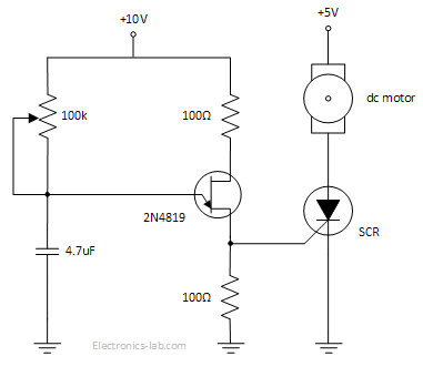
This is a variable speed DC motor controller using a UJT, a SCR and few passive components. UJT along with resistors and capacitor form an oscillator that supplies AC voltage to the gate of SCR. When the gate voltage exceeds the triggering voltage of SCR, the SCR turns ON and motor is running. By adjusting the potentiometer the output frequency of oscillator is changing and thus the times the SCR triggered is changing, which in turn changes the speed of the motor. In this way the motor is receiving a series of pulses that average over time and the speed is adjusted.
Basic TRIAC Applications
AC Light Dimmer
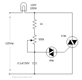
This is an AC light dimmer formed by a diac, a triac and some passive components. The capacitor is charging through the two resistors and when the voltage on one end of the diac exceeds the breakdown voltage it goes ON and sends a current to the gate of triac putting the triac to ON state and thus powering the lamp. After the capacitor is discharged to a voltage below the breakdown voltage of diac, the diac, triac and lamp turn off. Then the capacitor is charged again and so on. So the lamp is only powered for a fraction of time during the full sinewave. This happens very quickly and the lamp seems dimmed. Brightness is adjusted using the potentiometer.






fierst time i saw such cct of dimmer ever in my life
How does the DC motor circuit turn off? Usually SCR DC motor controllers are more complicated to allow the SCR to turn off.
This is a pretty simple SCR application circuit so it has basic functionality. To turn the motor off you will have to remove power.
A wire could do the same thing…conduct current as long as power is on 🙂