


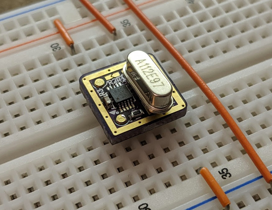
Most microcontroller implementation these days, use the traditional capacitor + crystal approach to generate their clock, this approach sometimes, however, lead to problems, especially when used in prototyping situations with a breadboard, jumper wires, etc., all of which have an (unknown) inherent capacitance that could lead to the clean 8 or 16MHz signal we desire, becoming noisy. A (now regarded as old school) approach to eliminating this is to use a full-can or half-can oscillator which usually comprises the crystal and other elements of the oscillator circuits. However, with advances in microcontroller technologies relegating the need for these oscillators, manufacturers are discontinuing legacy product lines and it’s becoming harder and harder to find through-hole versions of the full/half can packages. To give the OG’s another option, Schlae recently developed a breadboard friendly PCB version of the full-can and half-can oscillator package called ClockInACan.
According to Schlae, the ClockInACan is a small circuit board that comes in the form factor of the full-can and half-can oscillators and performs the same exact function as the oscillators.
Some features of the oscillators include:
- Wide +2V to +5.5V power supply range
- Logic-level enable pin with internal pullup
- CMOS-compatible output
- Selectable divide ratio of 1, 1/2, 1/4, 1/8, 1/16, and 1/32
- Crystal footprint fits through-hole and many surface mount crystals
- Pins are breadboard compatible, and also fit in DIP sockets
The oscillators are super easy to use, and all you have to do is provide your own crystal of the desired frequency or a multiple of the desired frequency, and set the three solder jumpers to select the divide ratio.
To make the project easy to replicate, it is designed with readily available components. The basic bill of materials is provided in the table below and all components can be found on Mouser by searching with the Mouser Part Number.
| Q | Designator | Description | Mouser Part Number |
|---|---|---|---|
| 1 | U1 | Oscillator IC | 513-NJU6311RB2-TE1 |
| 1 | C1 | 0.1uF capacitor | 603-CC603KRX7R9BB104 |
| 0 | C2, C3 | Optional load caps | |
| 0 | R1, R2, R3 | Divider jumpers | |
| 1 | R4 | 0 ohm solder jumper | |
| 1 | Y1 | Crystal | |
| 4 | J1, J7, J8, J14 | PCB pins | 575-0542000150000 |
The project is entirely open source and all the documents including schematics and PCB fab files for both the full-can and half-can oscillators are provided on the project’s Github page.
RELATED POSTS
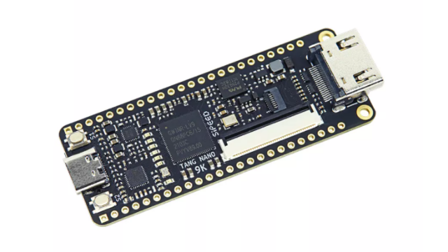 7 February, 2022 Sipeed Introduces Tang Nano 9K FPGA board, Compatible with RISC-V softcore PicoRV
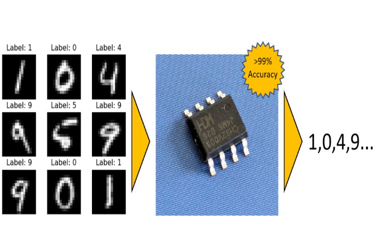 21 May, 2024 BitNetMCU Slims Down TinyML Models
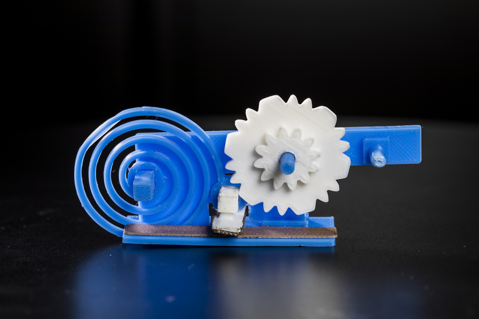 23 January, 2018 3D Printed Objects that can connect to Wi-Fi without any Electronics
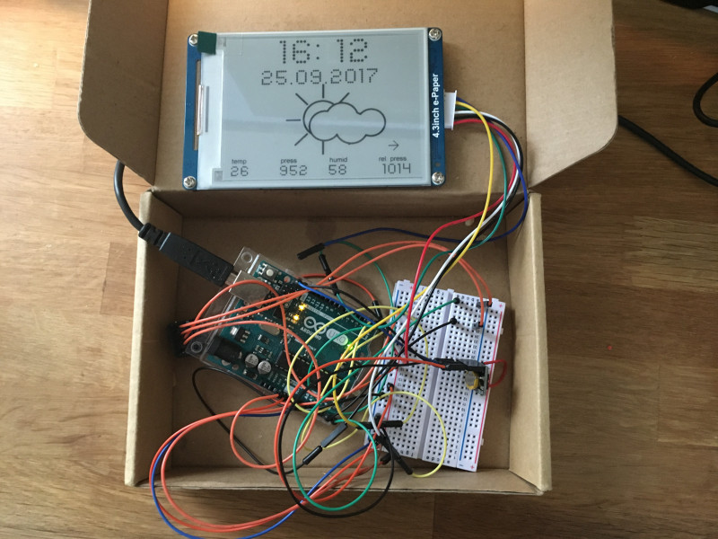 2 October, 2017 Arduino Weather Station With E-Ink Display
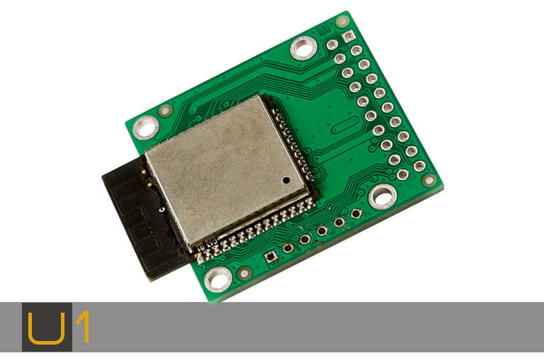 5 March, 2019 Novasom launches the SBC-U1 IoT SBC based on ESP32
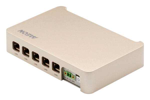 26 November, 2019 BOXER-8220AI: Powering AI with NVIDIA Jetson Nano