Demonstrating Automate Safe Cracking with an ESP8266 and a Stepper Motor
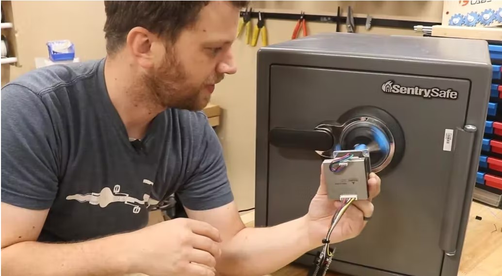
To recover a lost combination, we may see how YouTuber Zach Hipps designed and built a completely automated safe-breaking robot. Zach Hipps, who runs the YouTube channel Byte Sized Engineering, has a brother-in-law who put his safe’s combination code inside the safe just before going on vacation. But when he got home, he realized he had forgotten the code and couldn’t get it back, even after calling the company that made it. Hipps thought that he could try to solve the problem by making a safe-cracking machine from scratch that would try all one million possible combinations until it found the right one.
Mechanical design
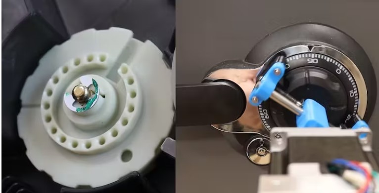
Hipps was looking into different kinds of robots that could open safes when he came across a video from the Lock Picking Lawyer that showed the ITL-2000. This is a robot that can automatically open a safe by turning the dial until the three inner rings line up. In order to improve the design and make it work better with other dials, Hipps kept the vertical placement of the stepper motor but replaced the chuck with a clamping mechanism that can adjust to different sizes. By doing this, damage to the safe is kept to a minimum, and it is also made very portable.
The components
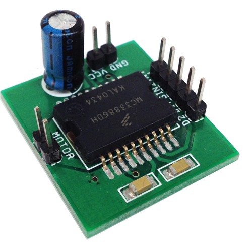
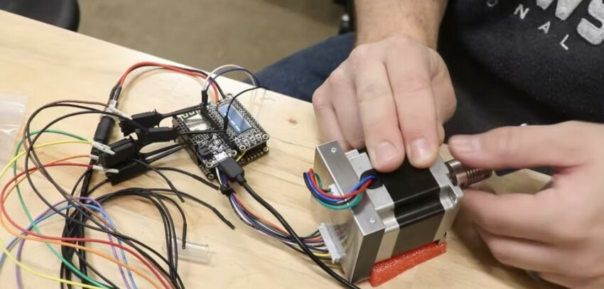
A stepper motor was needed to move the dial with fine, repeatable precision. Also, since the dial stops when the right combination has been entered, the microcontroller needs to know when the motor can no longer move. Hipps chose a PD57-2-1076 stepper motor because it has a high torque and a built-in motor driver that can also tell when the motor has stalled. An Adafruit ESP8266 Feather runs everything, and a stackable OLED screen lets you look at motor debugging data.

Handling motor stalls
The Trinamic driver for the stepper motor is built in, and it comes with a software package that lets you set certain parameters on a PC and send them to the driver over UART. After setting up the configuration, Hipps could see the load value in real-time in the software. A lower value meant that there was more weight on the motor’s shaft, and a value of zero meant that the motor had completely stopped. He then told the ESP8266 to keep an eye on this value, show it on the screen, and stop sending commands to move when a zero appears.
Wiring and assembling the device
The 3D-printed adjustable chuck works like a screw clamp. When you turn the threaded rod, each jaw moves either in or out, depending on which way you turn it. Hipps attached a coupler to the stepper motor and then used the two UART pins on the ESP8266 to connect it to the stepper motor driver. This allowed him to send commands and get the load value. Lastly, he put in a digital logic analyzer in case he needed to do more advanced debugging.

Initial tests
Hipps found a safe like the one in the Lock Picking Lawyer’s video and clamped the auto-chuck dialer’s around the dial to see if it worked as planned. From here, he held the stepper motor while the dial turned over and over according to a combination that had already been set up. This made sure that everything lined up correctly. In part two, he plans to build a frame to make it more stable and change the code to make it work better. If you want to learn more, you can watch his build log video here on YouTube.
