


In Sayanee’s Basu’s video, we can look at the design considerations in the process of taking a breadboard prototype to a custom PCB, from the microcontroller to the various subsystems, to the power, the bootloader, and even how to deal with faulty components.
A breadboard can be useful for educational purposes, art projects, and even small testing. However, when we need multiple units or the components required are only available in SMD or other non-standard packages, a PCB is mandatory. Another advantage of a custom-made PCB is the capability of producing smaller and more robust units in higher quantities, which leads to a better project overall.
The first design consideration is the microcontroller. Developing a schematic can be intimidating at first, but when you look at some open-source designs for the same MCU and the datasheet, you will feel more comfortable. This is also the step where you choose the package and the variant of the microcontroller you will use, using the datasheet’s ordering information section for guidance. Lastly, you should make sure to check the availability and stock from the vendor before doing the layout.
After choosing your microcontroller, you should look at the subsystem level, dividing the breadboard prototype into the different sections. DrawIO can be used to draw some quick flowcharts and connect the subsystems. You can also divide subsystems into 3 different colors, according to their category: power, microcontroller and sensors/actuators. Every box in your subsystem can later become a logical block in your schematic, separating the major functional areas of your system. You can also use solder jumpers or zero-ohm resistors in order to separate the functionalities of these subsystems, which can be useful to test each individual subsystem individually.
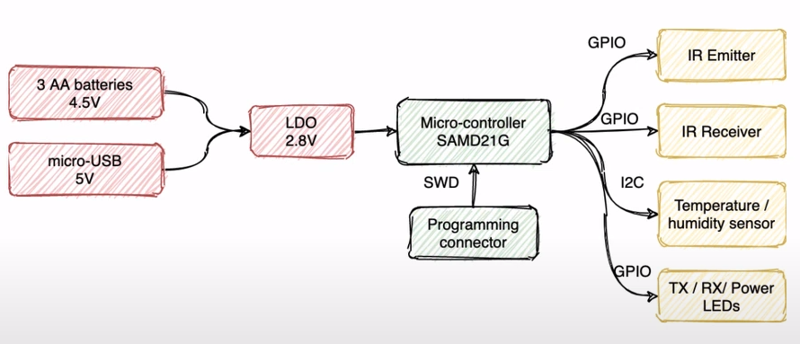
The next thing to take into consideration is power. You need to decide how your PCB is going to be powered, which can range from USB, alkaline, LiPo, or other types of batteries, or even a coin cell. You can even use more than one, but keep in mind extra circuitry may be required, otherwise, you can damage your entire PCB. Here, you can use online research and simulation to guide you. After deciding the power sources, you must choose a voltage regulator for the MCU, where you should refer to the microcontroller datasheet and look for the operating voltage and current, and then choose one that fits the criteria. Make sure to also check the maximum ratings of all the components, to ensure their compatibility with the rest of the circuit. You can also create a power tree, illustrating the main power flow through a tree of power converters that convert the supply power to the voltage and current required to drive the various loads. You should also consider incorporating a power switch, which can come in handy to debug, and a reverse-polarity protection circuit, which in its simplest form is a Schottky diode.
The next design consideration is the bootloader, which is important to upload the firmware you developed into the MCU, which will come bare from the factory. To this, you should refer the available interfaces in your MCU datasheet, along with the pins the said interface connects to. You also need to ensure you have the reset circuit for the microcontroller, which is necessary to upload the code into your board and to reset the board. This is often one of the scariest parts because it generally can’t be performed on the development board.
The last things to take into consideration are the sensors and the actuators. You should browse the datasheet of each of them to check at least the reference application circuit, to then replicate it into your PCB. To detect faulty sensors/actuators or even a design error, you should populate 2 or 3 PCB’s, because if one of them is working, then you can assume faulty component, but when none work, then you should review your design, because there may be something wrong with it.
Lastly, you can optionally include some LED’s on the power and bootloader pins, for debugging purposes, in your first prototype.
Hopefully, these tips will lead you to better PCB’s, the ones that work on the first try!
RELATED POSTS
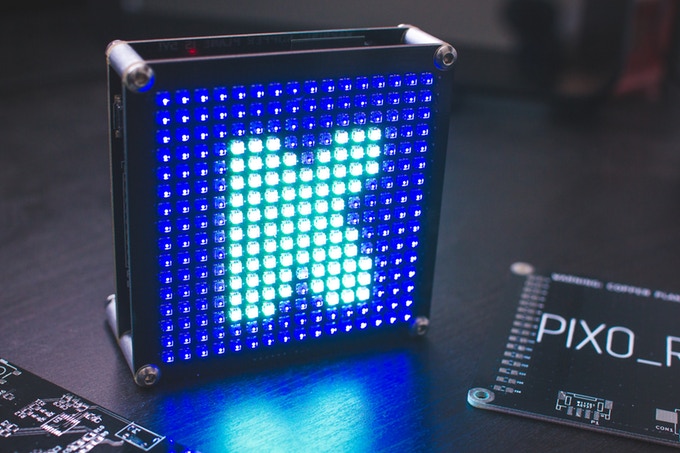 1 February, 2018 PIXO Pixel – An ESP32 Based IoT RGB Display
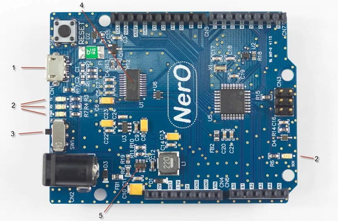 14 December, 2015 NerO – An Energy Efficient Arduino UNO Compatible Design
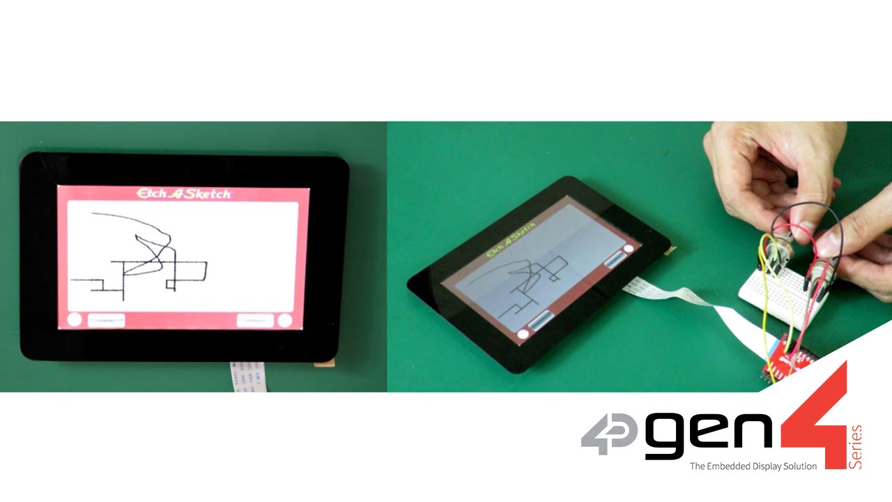 3 November, 2016 Etch a Sketch featuring gen4-uLCD-50DT
 14 September, 2022 DOOGEE V30 Series Positioned To Lead the High-end Rugged Smartphone Market with Dimensity 900 Chipset
 3 October, 2023 AAEON Unveils UP Squared i12 Edge: A Compact Powerhouse for Industrial Automation
 25 January, 2017 Expand Your ESP8266 Analog Inputs With $10


In reality, for a competent designer – you simply just draw the PCB manually off the top of your head reverting back and forth from the schematic (done it a million times) If the end result is electrically correct and it looks neat in appearance, then this is a hobby or trade for you. Otherwise, throw everything in the bin and try another industry to study or work in.