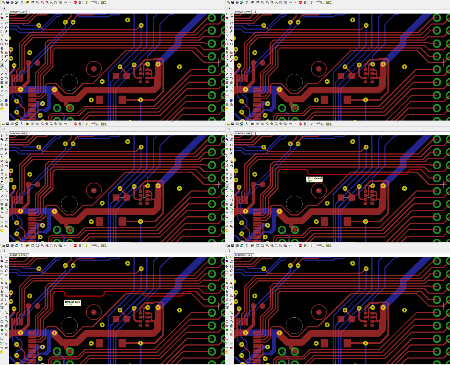
When you see some board designs, especially ones with high speed signals or differential pair signals, then you will notice a lot of zigzag/meander lines on PCB.
If you’re wondering whether you can do differential pair routing, then the answer is simply yes by using Meander tool.
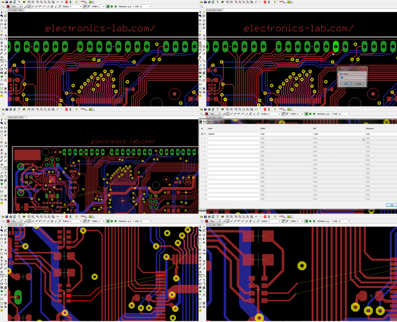
First, let’s see how we can draw Differential Pair in Eagle. To do so, follow these steps:
- Select two lines, give one of them any descriptive name you want ended with _n and the give the name to the other except that it should be ended with _p.
- When you route them, you will notice that trace is drawn for both of them, if you want to trace just one, then you need to press esc.
- You can determine the clearance between both of them while drawing by changing clearance value from default class (type “class” in command line).
Now, to use Meander tool, follow these steps:
- Select Meander Tool from the left sidebar.
- When you click on any route, you will see the length of this route. You will need to select a reference length to measure if you want Menders to match the length. Note that there is
no need to have any special name for these two lines. To select the reference wire click ctrl+left mouse button on the trace. Now hit on any trace with left mouse button and it will be compared to the reference length (a percentage will be shown). - If you failed to draw the Meanders, then try a smaller value of clearance for default class (type “class” in command line).
Subscribe
Login
1 Comment


